OPA548EVM: Using OPA548EVM to drive Thorlabs VCFL35 voice coil flexure scanner

Part Number: OPA548EVM
Other Parts Discussed in Thread: OPA548, OPA547EVM, OPA547, OPA549, OPA541

Part Number: OPA548EVM
Other Parts Discussed: OPA548, OPA547EVM, OPA547
Hello TI Support,

I would like to use the OPA548EVM as a linear amplifier to drive a Thorlabs VCFL35 voice coil flexure scanner from a function generator.

The VCFL35 load specifications are:
- Coil resistance: 2.2 ohm at 23°C, increasing up to about 2.75 ohm when warm
- Coil inductance: 167 µH
- Maximum continuous input voltage: 3.1 VRMS
- Maximum continuous current: 1.4 A at 23°C
- Force constant: 0.71 N/A
- Intended operation: mainly sine and filtered triangle waveforms, up to about 30 Hz for full stroke, possibly smaller amplitude at higher frequencies

I understand that the OPA548EVM supports dual supply operation up to ±30 V, and that the OPA548 can provide approximately 3 A continuous output current with adjustable current limit and thermal shutdown protection.

My intended configuration is:
- OPA548EVM, not OPA547EVM
- Dual supply, probably ±12 V
- Non-inverting voltage amplifier, initially Gain = 1
- Function generator connected to the EVM input
- VCFL35 connected as external load through the EVM banana output connectors
- Current limit adjusted to protect the VCFL35, initially around 1.1–1.2 A, with an absolute maximum not exceeding 1.4 A RMS
- Additional heatsinking if needed

Questions:

1. Is the OPA548EVM suitable for driving this type of low-resistance inductive voice coil load in voltage-drive mode?

2. For this application, would TI recommend using the standard non-inverting voltage amplifier configuration, or the Improved Howland Current Pump configuration?

3. If using voltage-drive mode, are there recommended stability components for the 2.2 ohm + 167 µH load, such as:
   - series output isolation resistor
   - Zobel network
   - feedback capacitor
   - changes to Riso, Rhcp, Cf1, or Cf2 on the EVM?

4. What supply voltage would TI recommend in order to minimize amplifier dissipation while still allowing clean output swing up to 3.1 VRMS across the load?
   Would ±12 V be reasonable?

5. What is the recommended method to set the OPA548EVM current limit for a maximum load current of 1.4 A RMS?
   The EVM user guide states that the default 14.7 kohm RCL gives approximately 2.5 A for OPA548. Should RCL be increased to around 26–33 kohm  for this load, or should the value be calculated differently from the OPA548 datasheet?

6. Are there any thermal concerns with continuous sine operation near 3.1 VRMS into 2.2 ohm?
   Is the EVM heatsink sufficient, or should a larger heatsink/fan be used?

7. Are there known limitations of the OPA548EVM when driving voice coils or similar inductive electromechanical loads from a function generator?

8. If OPA548EVM is not the best solution, would TI recommend another TI device or EVM for this application, such as OPA549 or another power op amp?

The goal is a safe lab setup for open-loop operation of the VCFL35 using sine and filtered triangle waveforms, with protection against overcurrent, clipping, oscillation, and thermal shutdown.

Thank you.
  • Hi Ilan,

    Thanks for all of the details here regarding your setup!

    1. Is the OPA548EVM suitable for driving this type of low-resistance inductive voice coil load in voltage-drive mode?

    OPA548 is a perfect pick for the range you are targeting. 

    2. For this application, would TI recommend using the standard non-inverting voltage amplifier configuration, or the Improved Howland Current Pump configuration?

    Non-inverting is the simple approach. Howland can be especially nice for very reactive loads, though the additional components of the HCP can add some complexity to the design + additional power loss through the current sense resistor. I think both solutions would work for your intended use-case. 

    3. If using voltage-drive mode, are there recommended stability components for the 2.2 ohm + 167 µH load, such as:
       - series output isolation resistor
       - Zobel network
       - feedback capacitor
       - changes to Riso, Rhcp, Cf1, or Cf2 on the EVM?

    I tried to avoid the series isolation resistor on your design, though we could add this if you want. 

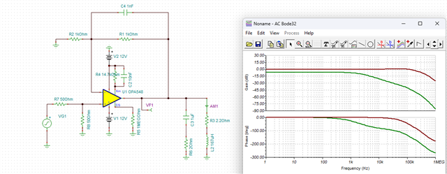
    I configured the amplifier in a gain of 2V/V with a 1/2 attenuator on the frontend. I use a 1nF CF and an aggressive 1uF + 2Ohm snubber. I assume you have a 50Ohm source impedance for the Fgen, though this could be made a higher resistive divider if you want to operate Hi-Z output on the generator. 

    You are welcome to play around with values and make changes as you see fit.

    Simulating the closed loop response gives us a very flat frequency response over frequency:


    4. What supply voltage would TI recommend in order to minimize amplifier dissipation while still allowing clean output swing up to 3.1 VRMS across the load?
       Would ±12 V be reasonable?

    +-12V is fine, though +-10V may be preferred if this voltage is adjustable. 

    5. What is the recommended method to set the OPA548EVM current limit for a maximum load current of 1.4 A RMS?
       The EVM user guide states that the default 14.7 kohm RCL gives approximately 2.5 A for OPA548. Should RCL be increased to around 26–33 kohm  for this load, or should the value be calculated differently from the OPA548 datasheet?

    Correct, somewhere in this range. Note, we should apply some guard band from your maximum expected current to account for natural errors in the current limit circuitry. For example, if I were using a current source of 1A maximum, I might set my limit to 1.2A. 

    6. Are there any thermal concerns with continuous sine operation near 3.1 VRMS into 2.2 ohm?
       Is the EVM heatsink sufficient, or should a larger heatsink/fan be used?

    Here is another simulation, this time showing Pd in the IC. Remember, power delivered to the load can often times be less than the power dissipated inside the IC. 

    Here PD(W) represents the power dissipated inside the IC. Here, RMS current is about 10W with a +12V supply

    If we reduce to +-10V supply, we now have just 7.8W RMS. 

    Now we can pass this information to our thermal design. 

    Here is the PN for the heatsink on the EVM: Aavid Thermalloy 530002B02500G (2.6C/W)

    If we have ~5C/W total Theta JA with the EVM heatsink, we could expect ~50C increase in junction temperature at +-12V supply with the expected load. Note, very low frequency signals should not always be treated from an RMS power perspective. It is good that we have enough thermal headroom here to not be too worried for entering thermal shutdown. It all goes to say that a fan is likely not required for this setup, however an elevated ambient temperature could change this. 

    7. Are there known limitations of the OPA548EVM when driving voice coils or similar inductive electromechanical loads from a function generator?

    Sometimes we have some amount of crossover distortion with these devices when the current is significantly out of phase from voltage. In this case, we should not see much of this since the load is tied to GND, and the snubber helps shift the phase current to be more in line with voltage. Otherwise, no real drawback with the Fgen. Non-inverting is nice in this respect as the Fgen is effectively separated from the high power output.

    8. If OPA548EVM is not the best solution, would TI recommend another TI device or EVM for this application, such as OPA549 or another power op amp?

    I think OPA548 is our best option here, and it has an EVM. Something like OPA549 or OPA541 could work, though we do not have a web available EVM. Is this for prototyping work, or is there a need to design custom hardware for your implementation?

    Thanks,

    Jacob