INA302: Current Sensing in Bidirection

Part Number: INA302
Other Parts Discussed in Thread: INA303

Hi 

I am trying to simulate the INA302 using TINA. I was able to sense and trip current as expected in one direction whereas I am not able to trip current in the other direction, however the current measurement in both the directions are accurate. How do i make the sensor to trip in both directions of current. For your reference I have attached an image of my simulation circuit.
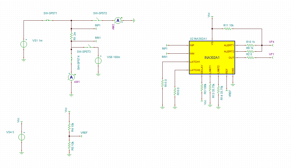
image.png

  • Sibi, 

    The issue here is the device itself. You are simulating with the INA302, which is a dual same direction comparator, but for two-level unidirectional tripping. For a window style (ie, positive and negative trip), you need to use the INA303:

    The INA302 has two independent triggers that operate in the same direction to deliver a warning and critical mode. As both the limit pins are set for the same value, they are tripping at the same time. Migration to the INA303 should see this move to the negative side of the range for an undercurrent mode. 

  • Hi Carlos 

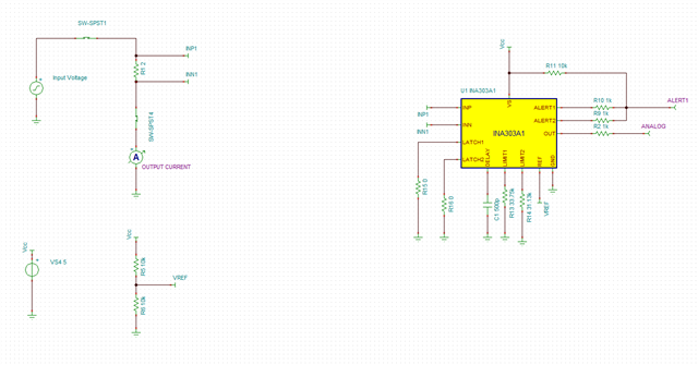
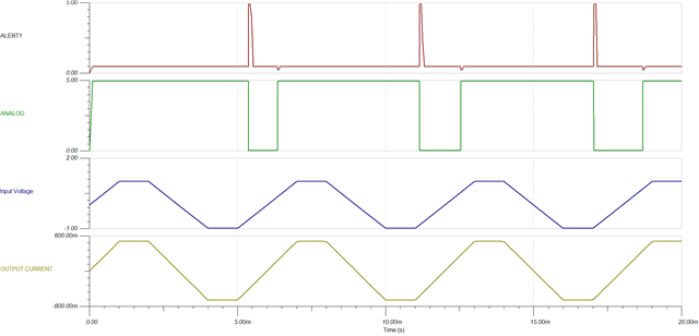
    As you suggested I tried to simulate using the INA303 and still the current tripping is not as expected. I have attached the image of my simulation circuit and the output plots

  • Sibi, 

    What scenario exactly are you trying to simulate here? Looking at your schematic, you currently have the window comparator values set to trip at 5mA (LIMIT1), and -240uA (LIMIT2), are these the intended trip points you are looking to measure here?

    You also need to have a look at your setup in terms of the amplifier itself, as the comparators are linked to the output and the values chosen for the design, and they need to be in linear operation to function properly. It is a 5V output maximum on VOUT, as per the supply. You are using the shunt resistor itself to set current with no load, and as such are sending over +/-500mA across 2Ω, which is producing +/-1V of sense at the inputs. Amplified by 20V/V, this will quickly rail the amplifier in both directions. this is theoretically attempting to output +/- 20V on the output, whereas the maximum ideal input is +/-125mV for a bidirectional use case. 125mV * 20V/V is 2.5V, stacked on the 2.5V reference to achieve 5V ideal (I say ideal because you also need to account for swing limitations as per the datasheet).

    I would recommend utilizing a standard sense resistor and using a current source as a load to set the desired current operation. This will simplify the input structure and give you more flexibility in the test conditions (I have implemented this method in the model below)

    Finally, If you are attempting an OR configuration here for the ALERTs, be careful on the resistor values chosen. When one side pulls down, its going to form a resistor divider with the other ALERT pin.

    I've taken the liberty of setting up a model using the above method I mentioned, and set it up such that it triggers at +/-500mA, and implemented an OR configuration for you. Let me know thoughts on the above and how I can help you with your application here. 

     INA303 OR Config.TSC