TAS6684-Q1: TAS6684 Schematics Review

Part Number: TAS6684-Q1

Hi TI Experts,

We have designed a schematic using TAS6684-Q1 for Automotive IVI system project. 

Please review the schematic and let us know your comments.

Key parameters/design requirements are-

  • BTL configuration
  • 4 ohm speakers 
  • 25 W/channel -RMS power
  • PVDD up to 36 V , Nominal VBAT 12V, and we need to test with 24V also.

The schematic and BOM are attached. Kindly review and let us know if there are any concerns or recommendations regarding the power  PVDD Caps, output filter, and overall component selection and design.

SCH- AMP_TAS6684_SCH_01.pdf 

BOM-AMP_TAS6684_BOM_01.xlsx 

Thank you for your support.


  • Hi Adarsh,

    The schematic looks fine, no issues found.

    Best Regards,

    Ethan

  • Hi Ethan,

    Many thanks for your feedback.

    We have some queries regarding the design also.

    Could you please clarify those.

    1. Since we are using only two of the four available audio output channels (CH1 and CH2), we have provided the bulk electrolytic capacitors (560 uF) only on the PVDD pins associated with the CH1 and CH2 driver stage power supplies. Could you please confirm whether this implementation is correct as per our schematic?

    CH1 OUT - PVDD PINS - Pin 23 ,24 

    CH2 OUT - PVDD PINS - Pin 32 ,33 

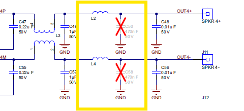
    2. In the audio output stage, we have provided only a single LC filter (10uH+1uF as per the LC design calculator available from TI). However, in the TAS6684 EVM schematic, we can see that two LC filters are provided at the speaker output pins. Is the additional LC filter necessary for our design?

    We have attached a snippet of the EVM schematic below for reference.

    3. Is there any recommendation for not used OUT, BST pins, NC is ok?

    Regards,

    Adarsh.

  • Hi Adarsh,

    1.The implementation is correct.

    2.Since the PVDD is 8-36V. In order to pass EMI test, additional LC filter (1uH+220nF) is needed.

    3.NC is OK.

    Best Regards,

    Ethan