OPA227: OPA227 constant current source driver circuit

Part Number: OPA227
Other Parts Discussed in Thread: OPA277, OPA192

Hi TI expert

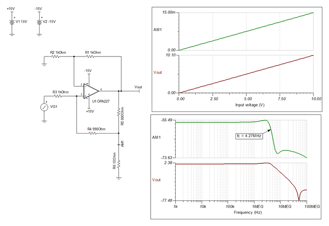
The attachment is the constant current source driver circuit for the OPA227. R4 is the load and is at high side. Now, due to a specific requirement, R4 needs to be connected to ground(low side). How should this constant current source circuit be modified to achieve this?
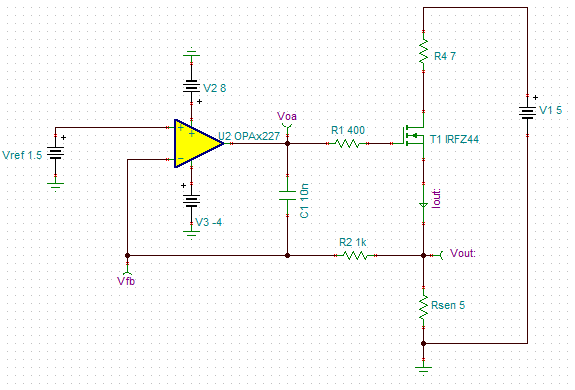
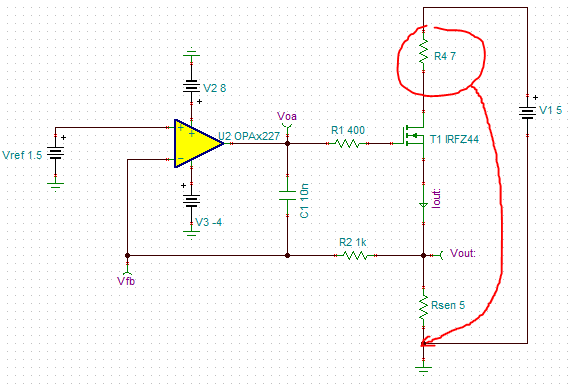
image.png

image.png

Best regards

  • Li,

    You could use the Howland Current Pump with a discrete power transistor output stage.  The simplest solution would only use one transistor, and would only be able to source current.  Let me know if you think this approach would work for you and I can help design the circuit.

    Best regards, Art

  • Hi Art

    I hope you can help me design a Howland current source circuit. Vref is a tunable sine wave, with a minimum of 5MHz, preferably 10MHz.

    Best regards, Li

  • Li,

    Below is a Howland current source.  To further refine this design you need to let me know the output current transfer function Iout/Vin.

    holland-current-pump.TSC

    Best regards, Art

  • Hi Art

    The circuit in the attachment has a very small output current. I need the output current to be adjustable from 0 to 0.3A. The input sine wave signal can have a bandwidth up to 5MHz, which means the current signal through the load R6 can also go up to 5MHz. The load R6 is an LED, about 3~5Ω, you can start by simulating with 5Ω.

    Best regards, Li

  • Hello, 

    Art is out of the office today and will return tomorrow. 

    Best Regards, 

    Chris Featherstone

  • Li,

    • Below is a circuit that will output 0mA to 400mA for a 0V to 10V input.
    • You can adjust the function of this circuit using by adjusting R7 and R5.  “Improved” Howland current pump circuit explains the operation of the circuit.
    • The transistor used is a simple NPN power transistor: DXT696BK  . There are many other options that will work.  
    • For the power transistor: make sure you choose R7 to provide enough base current for the function.  Look at hfe (current gain).
    • For the power transistor: make sure you connect the tab to a plane as a heat sink.  Op Amp with Single Discrete Bipolar Transistor Output Drive covers using a power transistor with an op amp.  It is not a holland current pump, but is a high output current op amp circuit.  You will need to confirm that your circuit can handle the required power dissipation.  I selected DXT696 because is has a low thermal resistance, high output current, and good power dissipation capability.  Pay special attention to notes 5,6, and 7 in the DXT696BK data sheet.

    holland-current-pump-with-power-transistor.TSC

    Best regards, Art

  • Hi Art

    Thank you for your reply!

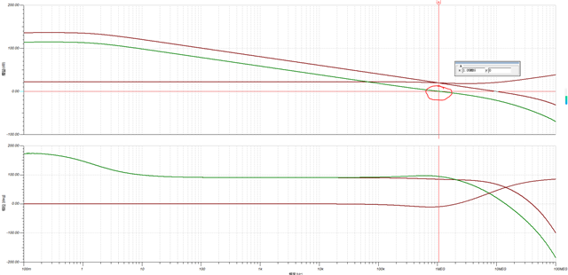
    I still have a question now. I modified your simulation file for VG1, R4, and R5—see the attachment. The input signal for VG1 has been changed to a 1MHz sine wave. R4 was changed to 5Ω because it's used for current sensing. The simulation results show that at an input frequency of 1MHz, Iout < VG1/R5, and the current signal Iout is somewhat attenuated. If VG1's frequency is increased to 5MHz, how should the circuit be modified? Do we need to replace U1 and T1?

    Best regards, Li

    1108.holland-current-pump-with-power-transistor.TSC

  • Li,

    1. I think that there are two issues: 
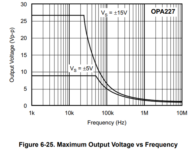
      1. Slew rate limitation. The slew-rate of OPA277 is not high enough for the 1MHz sine wave.  This limitation is also know as full power bandwidth limit or maximum output voltage vs. frequency. Full Power Bandwidth and Op Amp Distortion covers this topic in detail.   Below is the curve for the OPA227.  You can see that at about 20kHz to 40kHz the output swing becomes limited.  You can substitute the OPA227 with an amplifier with higher slew rate.  I did this with OPA192 (similar to OPA227 for DC precision) and the sinusoidal output looks relatively undistorted, but the output is clamped at near zero output voltage.  
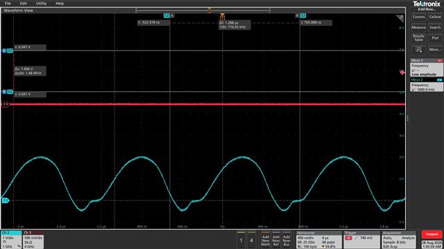
      2. The circuit cannot swing to ground.  This is why the output is clamped near GND.  Note that the op amp output will try to push its output high enough to keep the transistor on, but it does not work when Vin is near zero.  I added a 100mV shift on the input signal and the output looks pretty good.  If you want to swing to  Vout = 0V, you will probably need a push pull output (i.e. NPN and PNP).  Hopefully you can accept a small shift in the input signal as this circuit will be much simpler.  

    1108.holland-current-pump-with-power-transistor-opa192.TSC

    Best regards, Art

  • Hi Art

    Thank you for your reply!

  • Happy to help.

    Best regards, Art