THS4536: THS4536 - Design review

Part Number: THS4536
Other Parts Discussed in Thread: RES31A

Dear Technical support,

I woul like to ask you support in the design review of a current measurement circuit based on THS4536.

Curren range: -40 to 150 A

Minimum current that have to be read: 1 A

Shunt resistor: 200 uOhm

OUT+ and OUT- sent to SigmaDelta input of microcontroller.

I set the gain as 40 by means of R155-R152 and R154-R151: are the resistor values ok or bigger values are better with the same ratio?

Vcc = 3,3 V.THS4536.png
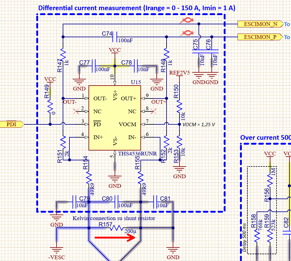
Could you have a look to the scheme in order to check if everything is ok, if you have any tips to improve the design or if other IC are better for my application?

Thank you in advance, with best regards

Stefano

  • Hi Stefano, 

    The resistor values you picked are appropriate for this design, and I would not recommend using bigger values even though the gain ratio will remain the same. If you decide to increase the resistor values, you will risk destabilizing the amp as it introduces several performance trade offs. The larger the resistor, the more thermal noise it can create, which will reduce your SNR performance as well.     

    Your design scheme looks good. I simulated it in TINA and your phase margin looks good as well. Since your circuit is for a current measurement, THS4536 should give you the most accurate performance since its offset voltage spec is the best among all the other FDAs we have. It has a typical Vos of 3 uV with a max of 20uV, so it should give you the least error when reading your current measurements. I wouldn't recommend any other IC if Vos is your priority.   

    Best,

    Amber Lee 

  • Hi Amber,

    many thanks for your reply.

    With best regards,

    Stefano

  • HI Amber,

    still on the same IC, I used another THS4536 for voltage measurement of a the 18S LiPo battery (Vmaxbatt = 75,6 V) and I would like to have a review of the scheme.

    A set a gain as 1 because the max voltage on the voltage divider is equal to 1,15 V at Vmax = 80 V), For the gain setting I used high precisione resistors (0,5%).

    The output signals are connected to a Sigma Delta ADC and will be read at 10 Hx

    Is this IC and this configuration suitable for my applications?

    With best regards,

    Stefano

  • Hi Stefan,

    I ran it through a simulation, and your PM is around 45 degrees, so it'll degrade a little but should still be stable enough. I would suggest using the RES60 (linked here: RES60A-Q1 data sheet, product information and support | TI.com) for your 137k resistor divider since it is all in one single package and can help simplify your circuit a bit more. The RES60 is typically used for attenuating battery voltages, which will work well for your resistor divider configuration as it also has a max voltage rating of 1400VDC. This can give you extra headroom for your Vmax of 80V. Another option could be the RES31A/21A, but it only has a max voltage rating of 85V, which might be a little too close to your limit. 

    Thanks,

    Amber
