OPA192-Q1: Attenuation

Part Number: OPA192-Q1
Other Parts Discussed in Thread: OPA192

I have a precision 5 V reference available at the IN+ input, and I need to generate an adjustable output range of 0 V to 1.5 V from this reference.

I would like to achieve this with very good accuracy and stability. Could you please recommend the appropriate op-amp configuration and resistor network to scale the 5 V reference to a 0–1.5 V output?

I would also like to understand what PCB provisions I should include to allow adjustment/calibration of the 0–1.5 V range output volatage. Output voltage requirement is 0 to 1.5V voltage that is generated with <0.25mV stability 

Could you please recommend a suitable TI precision op amp and the recommended circuit topology for converting the 5 V reference to a precise 0–1.5 V adjustable output?
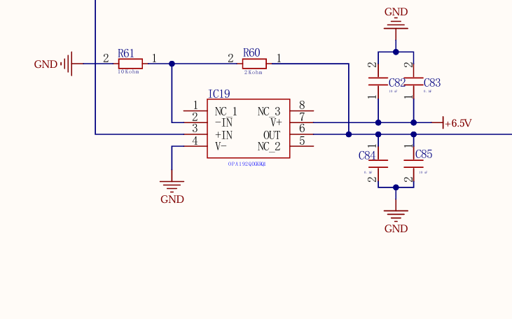
 image.png

  • Nishant,

    I need some information to help your out:

    1. You mention that you want an adjustable output range from 0V to 1.5V.  The circuit you show has a 5V reference connected to the non-inverting input.  This kind of circuit will have a fixed gain.  The gain is G = Rf/Rg +1.  The minimum gain of this circuit is 1.  Thus, the minimum output of this circuit is 5V.  Also, the circuit is not adjustable.  The output will be a fixed value.
    2. I show a circuit below that uses an attenuator and a buffer configuration to achieve a gain of less than 1.  I set the gain to 0.297 in this case.  The input is 5V and the output is 1.483V.  The analog engineer's calculator has a few tools to help select voltage divider components to achieve whatever  attenuation you need.  This circuit has a fixed output.
    3. If you want an adjustable output you will need a potentiometer or digital-to-analog converter (DAC).  An "old fashioned" analog potentiometer can be used to adjust the attenuation if you want something where a knob could be use to adjusted the output signal.  A digital potentiometer can do the same adjustment but would be controlled by a microcontroller. A DAC can be used if for the best accuracy.  Let me know what method you want to use to make the circuit adjustable.
    4. Your picture shows a capacitive load.  Connecting a capacitor to the output can cause instability.  In this context instability means that the amplifier would oscillate or output an AC waveform with the DC input.  This is an abnormal operation state and you need to compensate the amplifier to avoid this.  I show an example below where the OPA192 is driving 1.1uF with a 2.5 ohm isolation resistor.  Operational Amplifier Stability Theory and Compensation Methods  covers this topic in detail.  In this example I am using the snubber compensation shown in section 4.3.  I can help you choose compensation if you let me know your capacitive load.  

    opa192-atten-stability-open-loop.TSC

    opa192-tran-stability-test.TSC

    Best regards, Art