This thread has been locked.

If you have a related question, please click the "Ask a related question" button in the top right corner. The newly created question will be automatically linked to this question.

feedback resistors of inverting amplifier


I would have a simple question about feedback resistors of inverting amplifier. In the electrical diagram of differential amplifier used at the input of an ADC there is 1kOhm resistor between the signal input and amplifier input and two resistors (1kOhm and 47 Ohm) in series between this amplifier input and amplifier output. The ADC input is connected between these two resitors. Why? There is also a capacitor 1nF between amplifier input and output - I assume it works as an integrator. Another capacitor is connected at the ADC input. However, there is no serial resistor in front of this capacitor; so, this capacitor cannot work as a part of RC antialiasing filter, can it?
  • David,

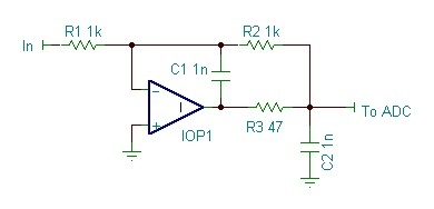
    I believe the circuit below is what you are describing... correct?

    There is more subtlety in this circuit than you might imagine.

    This circuit has a gain of -R2/R1 = -1. C1 working with R1 roll off the response at approximately 160kHz. Closing the feedback loop after R3 allows the amplifier to correct for any voltage drop in R3 in driving the load. R3 and C2 form what we sometimes call a "flywheel" driver for the ADC. This circuit allows C2 (just a wild guess of its value) to absorb the current glitches or pulses that are often produced by the input of the ADC. The whole circuit would typically be optimized for the particular combination of op amp and ADC to produce the best results for settling time or other dynamic behaviors. Sometimes the feedback loop is closed on the other side of R3.

    Hope this helps,   Bruce.

  • Dear Bruce, It is exactly what I meant. Thank you very much! I would have one more additional question - would you have an idea of choosing the value of the capacitors? I think that you can only slightly change the values of the resistors (the reasonable values are 1-10 kOhms) so the only way how to adjust the filter cut-off frequency are the capacitor values. Capacitors of about 1 microFarrad have much higher inductance and conductivity that could worsen the band stop attenuation at higher frequencies and influence the gain of the amplifier. The first issue can be corrected by a parallel capacitor of a small value but I have never seen it in this application.
  • David,

    R2 and C1 are chosen according to the required bandwidth. If bandwidth must be limited then capacitor values will become larger. It sounds like you are describing the series resistance and inductance of electrolytic capacitors. These would not be a good choice. Polycarbonate capacitors would be good in the 1uF range. Thee are many factors that could come into play when selecting a high value capacitor for very critical applications. Often, mylar types are adequate.

    Optimum values for R3 and C2 are very dependent on the op amp and data converter.

    Regards, Bruce.