OPA598: OPA598 - Short Protection

Part Number: OPA598
Other Parts Discussed in Thread: ISOM8600, DRV8350, ISOM8115, LMG5200, LMG2100R044, LM5088, LM5156, OPA593

Hello, this is Jin and thanks for the previous help. 


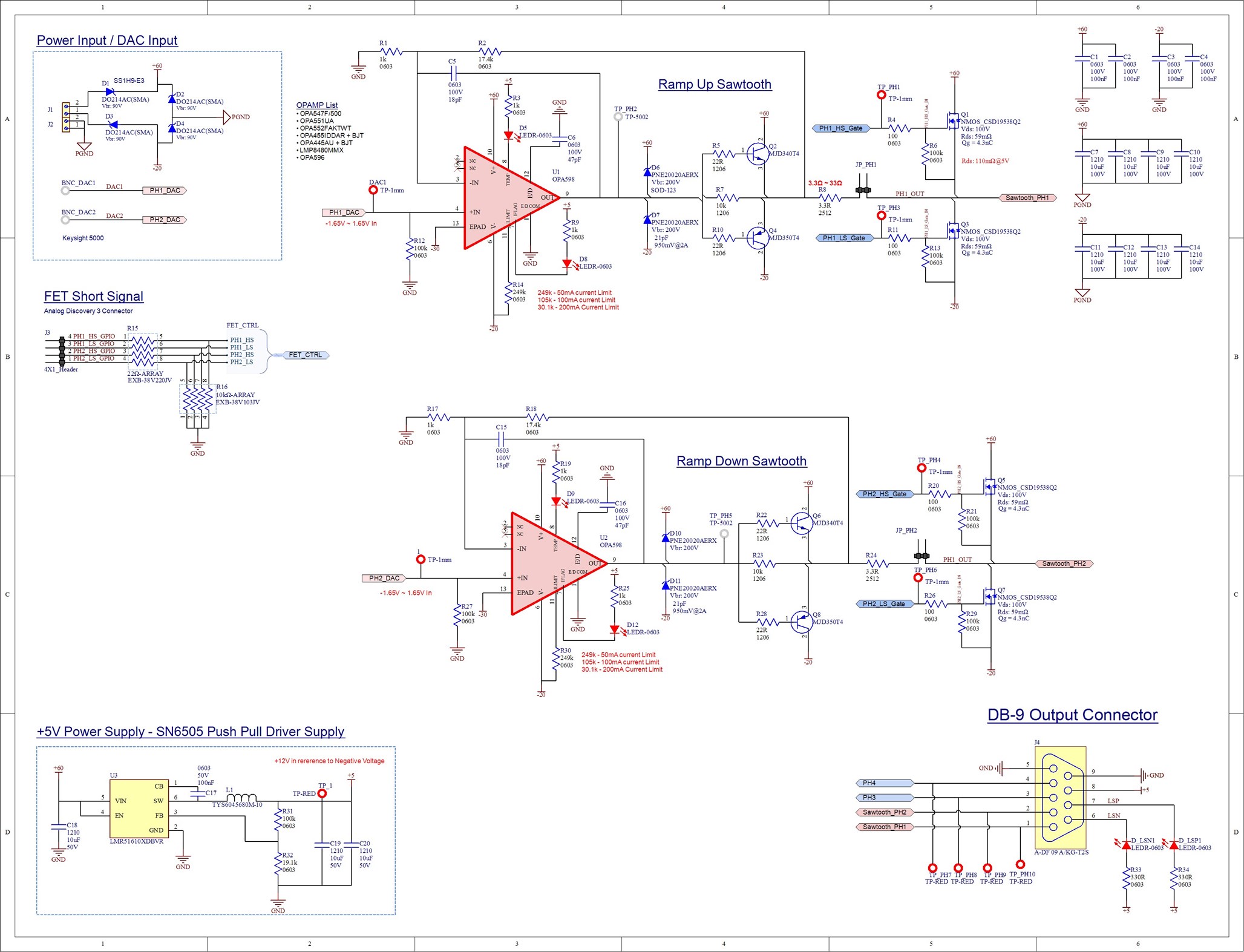
Compared to previous design, I am trying to make an compact sawtooth generator from +60V to -20V for driving an 150nF capacitative Load. 

In order to minimize the slew speed, I am going to add an half bridge at the output of opamp. 


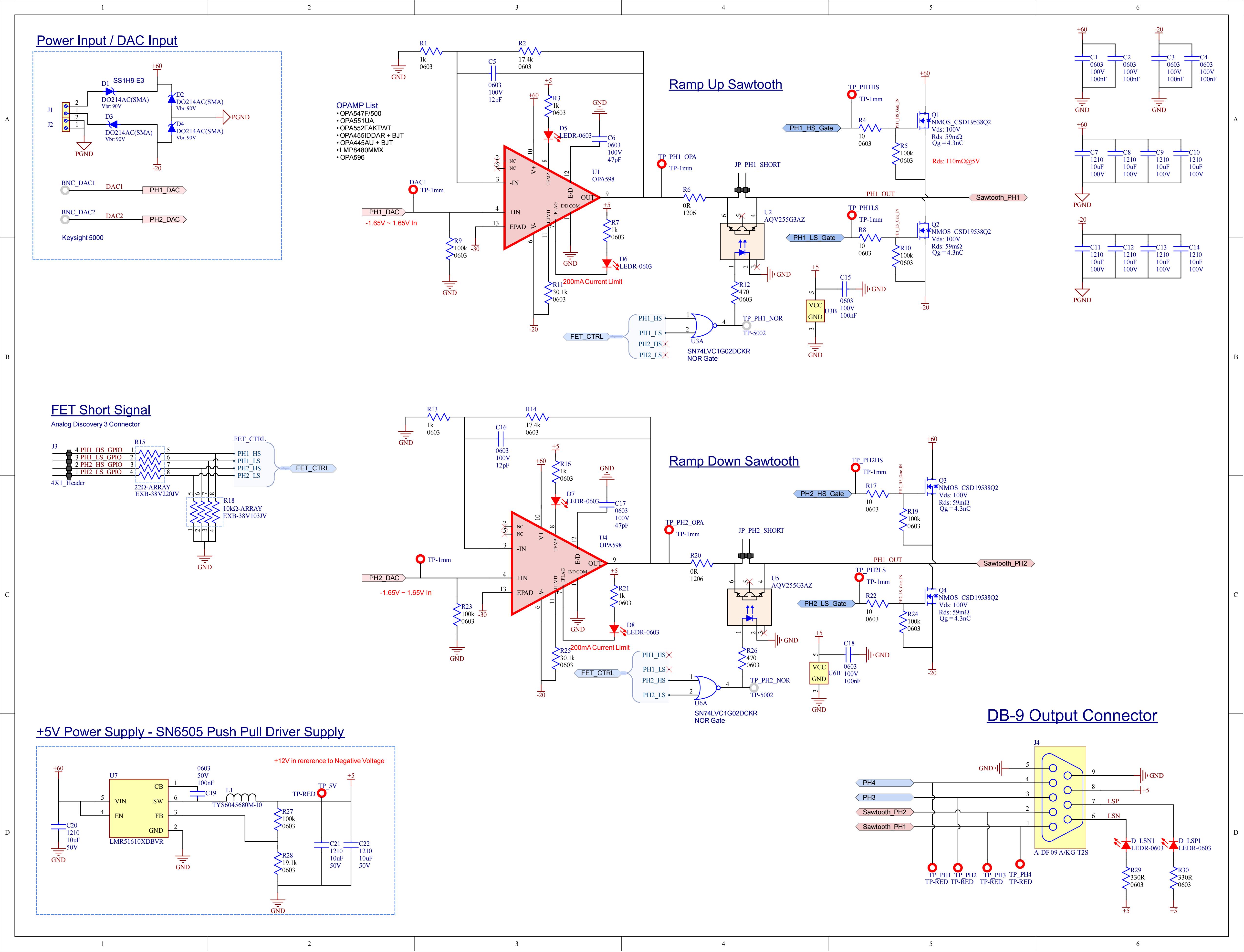
I initially thought about using an Optoisolator to isolate opamp from half bridge briefly, but the optoisolator takes too long time to shut down and turn on (same for OPA598 EN pins) for 10us. 

I've burned countless amout of OP-AMP (either opamp or FET burns) so I would prefer the signal isolation method, but I cannot find an suitable way to do it. 

Job1 conv 0.jpeg

I will change R6 and R20 to 22 ohm resistor and remove Optoisolator so that OPAMP directly have to withstand the shorting period. 

However, I am concerned that OP-AMP junction temperature might get too hot during shorting to VCC/GND. Will it be able to withstand the impact?  

Also, Is it better to just

  1. lower the current limit by I_limit resistor or
  2. Add an large resistor at the output side? 


Thanks for reading this. 

  • Hi Jin,

    Thanks for reaching out. 

    Just to confirm, this is for a new instrument, different from the original sawtooth generator we worked on, right?

    What is the maximum frequency/ slew time required?

    I will change R6 and R20 to 22 ohm resistor and remove Optoisolator so that OPAMP directly have to withstand the shorting period. 

    Yes, Riso may help the device sustain operation during electrical overstress, and improve stability of op amp operation. 22Ohm is a good place to start. 

    However, I am concerned that OP-AMP junction temperature might get too hot during shorting to VCC/GND. Will it be able to withstand the impact?  

    If the junction gets too hot during operation, the device will enter thermal shutdown. Sometimes this shutdown can create issues if the device was actively driving a reactive load. 

    It may be important to monitor the D7 LED during your operation to understand if this is occurring. The thermal shutdown can operate relatively fast, so it may be required to monitor short duration transients with an oscilloscope rather than just relying on the visual indicator of the LED. 

    I think the opto idea is unique and potentially a good way to solve the problem. Also, happy to see you are giving the NEXFET parts a try Slight smile

    Opto-couplers are traditionally pretty slow, and suffer from other concerns regarding temp rating and life expectancy. This is one of the reason TI developed Opto-emulators like ISOM8600. 

    These devices leverage multiple dies inside packaging to maintain a strong isolation barrier, but does not require slow Opto-electronics to transfer signaling. 

    Maybe this is worth consideration? 

    Also, Is it better to just

    1. lower the current limit by I_limit resistor or
    2. Add an large resistor at the output side? 

    I think we should start with the option 2, then check performance and determine if more change is required.

    If you find that OPA598 devices are becoming damaged even after the 22 ohm output series resistor, we should potentially consider adding Schottky diodes from OPA output to 60V and to 20V. These two diodes would help current steer in the event of EOS or reactive load kickback. Diodes like this are cheap protection that help improve reliability and stress tolerance of the op amp. 

    Please let me know what you think.

    Thanks!

    Best,

    Jacob

  • Yes, this one is for different application which will have an smaller PCB size than previous one. 

    Although the previous one worked out, we want to have an smaller, compact device with slew rate adjustable from 1us to 10us at 1khz ~ 10kh using TI DRV8350 IDRIVE feature. (By turning on gate slowly, we want to make sawtooth rise/fall slower than instantaneous rising/falling)

    The previous board burned OPAMP and DAC after trying to push 1us by removing feedback capacitor. 

    I checked ISOM8600/ISOM8115 but it is either slow to turn on or not able to pass -20V ~ 60V sawtooth signal with 100mAish current.

    Here is updated abstract schematic. I want to protect OPA598 as much as possible by putting an current booster just like previous design so that either FET or BJT gets damaged without Opamp, since Digikey OPA598 stock will return March 2027.


    Should I put an resistor between current booster stage and half bridge? 


    I tested this concept with GaNFET before (OPA547F + LMG2100R044/LMG5200) but the rising/falling edge was too fast (12ns from 0V to 60V), damaging the capacitive load. 

    There are some other minor circuit for +60V and -20V using LM5088 and LM5156 in schematic. 


    I attached full schematic in PDF. 

    8686.Job1.PDF


  • Hi JIn, 

    Thanks for sending over the full schematic, I see what we are looking to achieve. 

    I was less than familiar with this application, but now understand the goal of the sawtooth waveform for the Piezo-walking positioner. 

    I have not used the DRV8350 before, but I agree that the IDRIVE function may help manage the negative slew rate. 

    It is also good to know that you used a GaN FET in the past, proving that slew rate does need to be managed in order to protect the load. 

    OPA598 is still available on TI.com if you require additional material. 

    I think this strategy would work, though it would be interesting to see how the amplifier output will respond to the FET's activating. The protection diodes + resistance between the half bridge and the current booster should help offer some protection during the high negative slew event. 


    Should I put an resistor between current booster stage and half bridge? 

    Yes, we should do so, however this may need to be optimized through testing on bench. Excessive resistance will potentially dominate and control the maximum rate of change when linear control is required. 

    Overall however, I think that this is a great option where we see fast, but controlled edge rates when using the gate driver. We will still see good linear performance from the current booster + OPA593/OPA598. 

    The DRV unfortunately does not have an spice model, but I may be able to simulate with the assumption that the IDRIVE sufficiently regulates GET current. Are simulations helpful, or are you looking to go directly into prototype hardware?

    Thanks,

    Jacob