TLC2272-Q1: Current sensing, could not simulate real current waveform

Part Number: TLC2272-Q1
Other Parts Discussed in Thread: TINA-TI

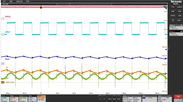
Shunt current sensing, below is the circuit, H-bridge drivering, low side shunt selection, 25KHZ PWM. the test wavefrom, "blue" is motor output currrent, "Green" is current ADC value, normal understanding, Motor FWD no current go through shunt, ADC should be =0, but a value is exist. what's the reason?
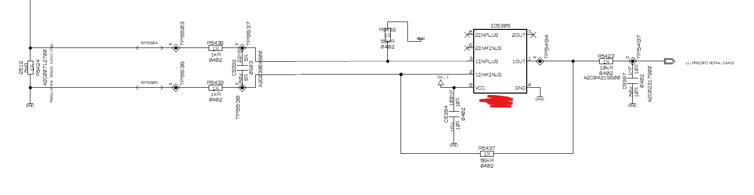
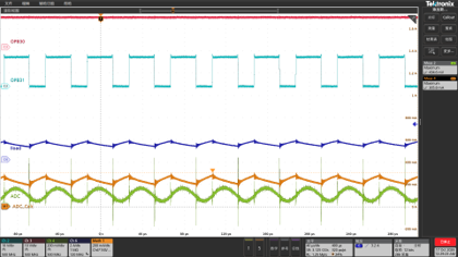
image.png

image.png

  • Hi Bing,

    I would be happy to help with this. To clarify, the issue is that the output of the amplifier does not go to 0V when the current through the shunt resistor is 0A, correct? 

    Unfortunately I can't read the horizontal and vertical scales for the waveforms in the image, could you send the oscilloscope capture in a higher resolution? Additionally, what is the amplitude of the input current waveform?

    I'm working on making a simulation of this circuit in TINA-TI. With 15A (DC) through the shunt resistor, the output voltage is 4.2V, and with 0A through the shunt resistor, the output voltage is 9.23mV. Once I know the input current amplitude in your circuit, I will try to replicate the transient behavior. 

    Best Regards,

    Alex Curtis

  • Hello Curtis

    below picture maybe more clear

    ...

  • Hi Bing,

    Thank you for the new images, this was very helpful. It appears that the current flowing through the shunt resistor (Iload) is never 0A. Based on the peak values shown in the image, the minimum value of Iload is approximately 1.25A, and the maximum is approximately 1.75A. 

    So even without the filter capacitors, the output of the current measurement circuit will not be close to 0V. With the filter capacitors, the output has significant delay, so the output does not have enough time to settle to the minimum value with a 25kHz input signal. 

    Please see the attached TINA simulation.

    TLC2272-Q1 Low Side Current Sense 10-20-26.TSC

    Kind Regards,

    Alex Curtis

  • Hello Curtis, Thank you for your help,   correct Motor current information, the Load current is Motor current, not current go through the shunt, only rising current will be go through shunt. And i would like to know whether do we have model could support LTSPICE?

  • Hi Bing,

    Could you please clarify what you mean by this? 

    Load current is Motor current, not current go through the shunt, only rising current will be go through shunt

    If the blue waveform "ILoad" is not the current flowing through the shunt resistor, I'm not sure how to interpret the images you've provided. If "ILoad" is not the actual input current to this amplifier circuit, could you provide a measurement of the current flowing through the shunt resistor, or the voltage between the test points TP5503 and TP5536?

    We do not make models for LTSPICE, however we do support TINA-TI and PSpice for TI. 

    Best Regards,

    Alex Curtis