A related question is a question created from another question. When the related question is created, it will be automatically linked to the original question.
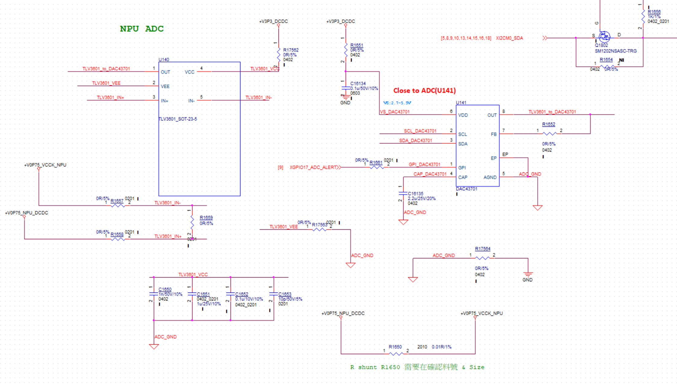
Would you please help review the schematic of TLV3601? And clarify if the caps C5~C12 on our evm can be removed for customer condition, 3.3V single supply?
Why do you have DAC output and the comparator output tied together?
The TLV3601 cannot disable it's push-pull output, so even if the DAC output can be disabled, the comparator would always win the battle.
Also, we do not recommend placing a resistor in series with the comparator VEE. VEE should go directly to ground. The TLV3601 is a high speed device with nanosecond rise/fall times, so transient currents of up to 100's of mA during output transition (H to L) can be on the VEE pin, raising the negative supply. If this resistor is needed, then there should also be a bank of capacitors on 3601_VEE (at least the smaller pf/nf ones).
If GND_NPU_VPROBE goes off-board or into a cable that goes outside the unit, it should probably tie to GND. That way external noise is not injected into the ADC_GND. If the sensor is within the board, then ground it to ADC_GND.