This thread has been locked.

If you have a related question, please click the "Ask a related question" button in the top right corner. The newly created question will be automatically linked to this question.

LoadCell and INA122 problem

Other Parts Discussed in Thread: INA122, TINA-TI

I have a problem using an instrumentation amplifier(INA122), here's datasheet:
http://www.ti.com/lit/ds/symlink/ina122.pdf
I've used the scheme in page 9 figure 5. Is powered by +5volt from arduino diecimila.
The bridge have 4 resistors of 350ohm (3 potenziometers and 1 strain gauge)(result Ro is 350ohm on Vin+-) powered too by +5volt from arduino. The problem is that the output is always 0v on Vout, so amplifier does not amplify my input imbalance when i change pression on strain gauge. I've tryed to change Rg but nothing, the output is always 0v. All connections are right and without short circuits.

I have done measures on Vin+ and Vin-, i've detected -2.3 milliVolt (due to the imprecision) and 3 milliVolt on output, and the output don't change if i change the voltage on Vin+/-(i've tyed within +-0.3 milliVolt, changing pressure on loadcell).

Maybe it does not amplifies because voltage on vin is negative?, i've not connected capacitor on V+ maybe this can be the problem?

What i'm doing wrong?

Ty for your help,
Yaro.

  • Hi Yaro,

    Are you using a current source for your bridge as shown in Figure 5 of the datasheet, or is the bridge connected directly to your 5V supply?

  • John Caldwell said:

    Hi Yaro,

    Are you using a current source for your bridge as shown in Figure 5 of the datasheet, or is the bridge connected directly to your 5V supply?

    I've connected +5V directly to the bridge from the same source that power INA122. Pin 4 and 5 going to gnd.

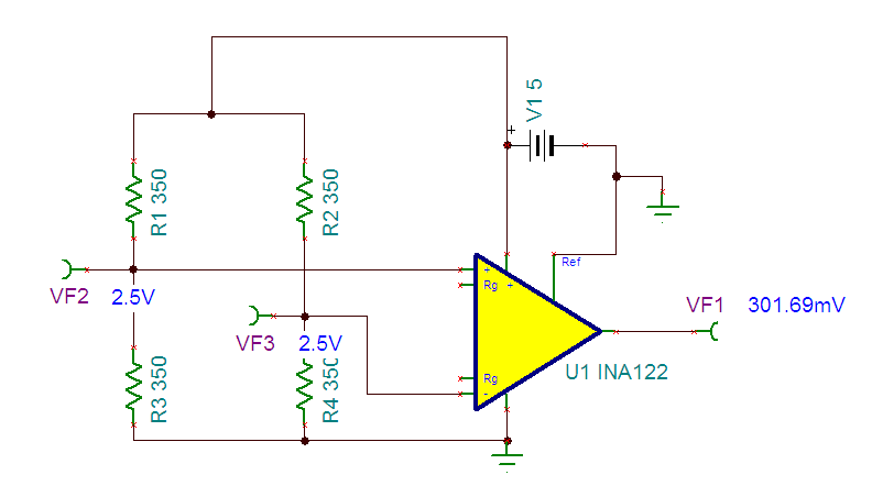
  • Ok, and to further clarify, what were the voltages at each input to the INA122 with respect to ground? For an unloaded condition I would expect each to be at 2.5V and the output of your circuit to be close to ground:

    I believe what may be causing the issue is which leg of the bridge you have each input of the INA122 connected to. For example, the above circuit will only function properly if the resistance of the strain gauge element (R4) decreases. Below I have plotted the output voltage with respect to the resistance of R4:

    With the reference pin tied to ground, the part will try to swing as close to ground as it can for no differential input voltage. Notice that the part becomes non-linear as it nears it's negative supply rail (GND). By tying the ref pin to a voltage of Vcc/2, you maximize the output swing the part is capable of:

    These simulations were done in Tina-TI using the DC transfer characteristic analysis. I've attached the simulation file if you would like to further simulate your circuit. Tina-TI is available for free from our website (http://www.ti.com/tool/tina-ti)

    INA122 Debug.TSC