This thread has been locked.

If you have a related question, please click the "Ask a related question" button in the top right corner. The newly created question will be automatically linked to this question.

Op Amp keeps drifting to rail

Other Parts Discussed in Thread: OPA340, OPA376

After years of working with op amps I'm stumped.

This should be op amps 101.  What scares me is that I'm gonna look real stupid for missing something simple.

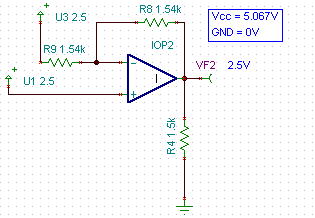
I tried both a OPA376 and OPA340 in the circuit below.

This is the sequence of events and measurements.

    1. Turn on Power
    2. Measure output = 2.5V
    3. Wait 10 seconds, measure output = 2.5V
    4. Wait 10 seconds, measure output = 2.5V
    5. Wait 10 seconds, measure output = 2.75V
    6. Wait 10 seconds, measure output = 3.46V
    7. Wait 10 seconds, measure output = 3.78V
    8. Wait 10 seconds, measure output = 4.34V
    9. Wait 10 seconds, measure output = 4.83V
    10. Wait 10 seconds, measure output = 4.98V
    11. Wait 10 seconds, measure output = 4.98V
    12. Turn off power, wait 30 seconds
    13. GoTo step 2
   
    IN+, IN-, Vcc remain constant throughout test.

The output keeps drifting to upper rail.

What is a list of things that could possibly cause this?

  • John,

    You are just in being baffeled by this one because there is nothing obvious in the circuit that you have given that would account for this behavior. If it were me I would start looking for a bad connection,  a cold solder joint,  or something of that nature. You might even have a feeback resistor that is "opening" up as the circuit sets there.  This type of issue could explain the slow drift to the rail.   It is definately not any thermal issue since you are running at around 5mW of power.   It has to be a bizzare connection issue or if you are using a socket for the Op Amp,  check and make sure that your not loosing continuity to each pin.  I once had a TO-99 socket that led me down a similar road of confusion because the contact pin was wallowed out and the Op Amp would intermittantly make contact.

    Daryl Hiser
    PA Op Amp Test

  • Daryl,

    Thank you for affirming my sanity.  Or at least letting me know that I am not alone in my doubts.

    Things I have done:

    1. Striped everything else off the board.
    2. Changed load resistor value
    3. Changed R9 and R8 values
    4. Tried 5 different op amps
    5. Rung out pads while unpopulated
    6. Rung out pads with components
    7. Monitored all input values while output on the rise to rail.
    8. Stared at it for hours, hoping to intimidate it into proper behavior.

    It would make more sense if it sunk to Vgnd.  Then I could assume it was overloaded and/or overheating.  That would lead me to look to some board anomaly that doesn't ring.

    What really confuses me is the time factor.  When it's cold, it takes 30-40 seconds to go to rail.  After the first time it moves more quickly.  This leads me to assume that I am somehow causing a thermal event.  But why would it go to rail high and not shut down?

    I think, I'll go stare at it some more.

    Regards

  • Hi John,

    What happens

    1. When you terminate your load to 2.5V instead of GND ?

    2. When you connect the non-inverting input to GND ?

    Regards,

    Jayant

  • John,

    I breadboarded up the circuit "exactly" as you have it drawn this morning because I couldn't believe that there was any issue with the circuit as drawn.  My bread board version of the circuit  is setting there with the output at 2.5V...(solid as sears) after 1 hour;   no oscillations, no output drift, no issues!   The only small differences that I had in my breadboard as compared witht he schematic that you posted was I used 1.5K resistors for all three resistors shown, and I put a 0.1uF Ceramic bypass capacitor between the supply pins....(old habit). 

    There *must* be a bad / intermittant connection to either one of your inputs, the negative supply pin, or the feedback resistor!   Sometimes these can "appear" to be thermal since changes in temp can cause the connection or cold solder joint to open and close ase the metal expands slightly.  This could be consistant with the behavior that you are describing     The only final possibility is that there is something else in the circuit that you haven't shown because you think that it is not significant.  

    I will keep the circuit powered up for the rest of the day and check back in this evening,  but I will say that I am pretty confident that there will not be any change...

    Regards,
    Daryl

  • Dearest Daryl,

    Many thanks for your initiative and support.  Unfortunately the problem no longer exists.

    I say unfortunately because I have not learned anything.

    I had two surface mount proto boards so I populated the second one today.

    I started just with the power supply, bypass capacitors, and resistors.

    I checked all my voltages and then added the op amp.  It worked just like so many op amp designs before, rock solid and according to the book.

    Regarding you suggestions and the problem board, I thought I had change out and checked everything multiple time.  Taking the op amp off and checking voltages, for continuity and for shorts. But I had had the problem for over a week before I came to the forum.  I have to believe that somehow I missed something that had a thermal issue.  But with 7 components I thought I couldn't miss it.  Oh Well.

    I might go back and change the two feed back resistors one more time.  But honestly I need to move forward.  The op amp is really part of a two pole filter so the next step is to add back all the capacitors and resistors that will make up the filter.

    Thank you for showing me that the circuit should work by doing it yourself.  That really convinced me to just go build it again on the other board.

    Regards,

    JohnK

  • Hi John,

    These problems drive me crazy! It never ceases to amaze me how a circuit with 6 or 7 components can make me question years of electrical engineering education...

    I wanted to add my two cents to the debugging process that come directly from head-scratching type problems I've had (mostly late at night) here in our labs in Tucson.

    1. Try cleaning the surface mount prototyping boards if you haven't already. Residue left over from the assembly of these boards can create leakage pathways that can cause all types of funny behavior. Flux seems to be just conductive enough to create unpredictable circuit results. If I'm doing assembly at work I wash my circuit boards with deionized water and and ESD safe soft bristle brush. If I'm building things at my lab at home it's more like tap water and a toothbrush. I think Bob Pease was quoted one time as saying he put his circuit boards through the dishwasher...

    2. If you are using a breadboard, build the circuit on a different area of the breadboard or a different breadboard all together. I had a very similar issue here on a circuit I was working on and the culprit turned out to be an internal defect in the breadboard I was using. I've also had a similar experience with protoboard (perforated or "donut" board).

    3. If you are using a pcb, and have access to a microscope or magnifying setup, check for hairline shorts between ground or power planes and your input traces. I had a pcb here that had insufficient clearance between a ground pour and an output trace and during assembly very small (only visible under a microscope) connections would be made where the solder mask melted and allowed solder to create a short.

    Good luck on finding the issue!