This thread has been locked.

If you have a related question, please click the "Ask a related question" button in the top right corner. The newly created question will be automatically linked to this question.

Problem with pH sensing circuit

Other Parts Discussed in Thread: INA116, INA121, LMP91200

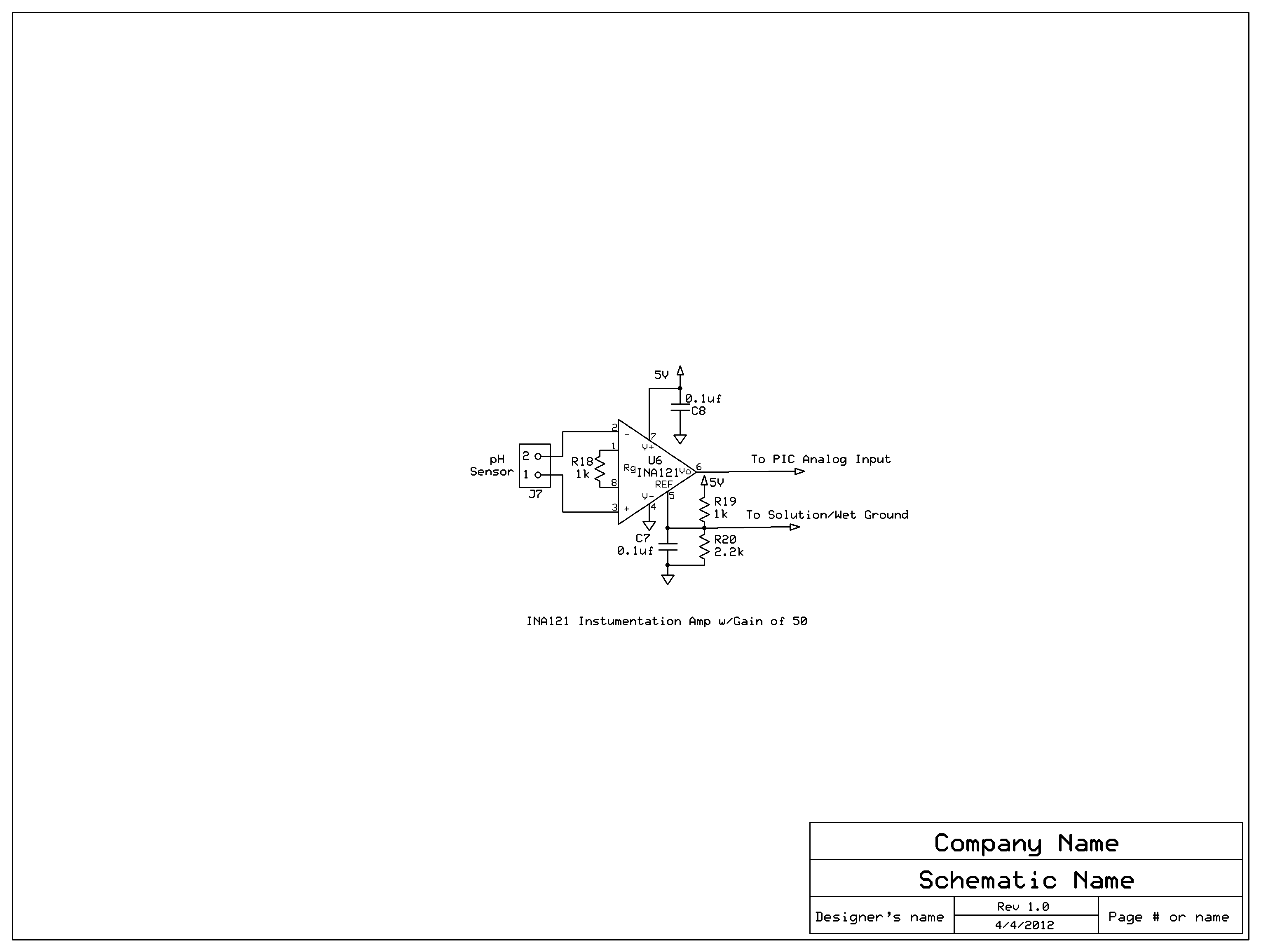
I have breadboarded a pH sensing circuit using the circuit shown on page 9, figure 7 of the INA116 data sheet using an INA121, and it works somewhat as expected.

Notes: I have V+ at 24 v, V- at ground, and Ref tied to a resistor voltage divider to provide a voltage offset on 3.5v to shift the pH swing (6.5 - 8) into the input range of a PIC ADC. I also use this voltage as the "Solution Ground". I am using a gain of 50. The pH sensor provides a +/-0.059 volt change for every unit of pH, with a pH of 7.0 being 0 volts.

I have now had boards made and the circuit does not work. I have cleaned the boards to insure there is no stray resistance.

Any assistance would be GREATLY appreciated!!!!!

Craig

  • Hello Craig,

    My first observation is that you will want to buffer the reference voltage coming from the voltage divider as discussed on page 8 of the INA121 PDS.

    Also, you state that it 'works somewhat as expected' yet later state that 'the circuit does not work'.  Can you please clarify these statements?  The schematic, scope and/or measurement values of the input and output, and perhaps the layout will help greatly.

  • Hello Pete and thank you VERY much for your quick reply.

    I have also tried using the output of a 78l05 voltage regulator as the reference/offset, and I have the same issue: the output seems to saturate to the negative supply (ground).

    The breadboarded version works pretty much as expected. When I put the pH sensor in water with a pH of 7.4, the output reads approximately 2.3 volts, which is correct: 3.5 - (0.4 x 0.06 x 50) = 2.3 volts. When I put the pH sensor in water with a pH of 6, the output goes up to around 6 volts, which is a little low: 3.5 + (0.06 x 50) = 6.5 volts.

    I had boards made and the circuit only drives the output to ground.

    Attached are the schematic of the pH circuit and the board layout.

    Thanks again!

    Craig

  • Hi Pete,

    I'm not sure how useful that layout image is, but the INA121 is U6.

    I tried uploading a dxf file, but it wouldn't allow it. I could e-mail it to you if you send me your address.

    Craig

  • Hi Pete,

    I'm not sure how useful that layout image is, but the INA121 is U6.

    I tried uploading a dxf file, but it wouldn't allow it. I could e-mail it to you if you send me your address.

    Here's the schematic.

    Craig

  • Hello Craig,

    Thanks for the additional information.  I can see the layout, but the schematic did not come through.  Can you please re-attach?

  • Hello Craig,

    I'm not sure how I missed the schematic, but I have it now.  Sorry about that.  We will look at this and get back with you soon.

  • Hi Pete,

    I could only attach one file at a time.

    Also, I misstated my results.

    I was using a 5v reference from the 78l05 and the reading on the "alkaline"" water was around 3.8 (as expected), but the "acid" water was reading around 6 volts, where it should have been reading around 8.

    I'll double check these results.

    Craig

  • Hi Craig,

    not really an answer to your question, but maybe helpful anyways. We have jsut introduced the LMP91200. This is a complete interface for pH probes. It contains anything you need, including extremely low input bias current, well below 1pA over temperature, active guarding, common ode offset and temperature mesurement support.

    Maybe if you have a look to the data sheet of this part, you want to redo your design? An move to this part, optimised for pH measurements.

    Andreas

  • Hello Andreas,

    Thanks for the reply.

    That looks like a great device, but it's not going to be available in production for at least 12 more weeks. I did order some samples though!

    I need an immediate-term solution. The LMP91200 could work longer term.

    Thanks again!

    Craig

  • Hello Craig,

    The INA121 requires a path for the input bias current.  It appears as though such a path is not provided for on the PCB. This is discussed on page 9 of the PDS. 

    The output voltage range is dependent on a variety of things, including the supply voltage, input common-mode voltage, gain, load, and Vref.  There are two graphs depicting this relationship on page 4 of the PDS.  While these graphs are for dual supplies, we can probably determine the output voltage range if you can give us your input common-mode voltage (we already know the gain, supply, Vref, and will assume the load is >10kohms). 

    Finall, the INA121's operation is referenced to GND.  What potential is the pH sensor referenced to?

  • Hi Pete,

    I was under the impression that the "Solution Ground" (as shown in the INA116 datasheet on page 9, figure 7) provided the bias current.

    As far as the input common mode voltage, and the pH sensor reference goes, and please excuse my ignorance,  wouldn't that also be dictated by the "Solution Ground", which is tied to Vref?

    Thanks!

    Craig

  • Hello Craig,

    Now I understand...thanks for the clarification.  Can you please explain the electrical connection (e.g. the SPICE model) between the solution ground and the electrodes for your pH sensor?

  • Hi Pete,

    I don't have a Spice model, I'm more "seat of the pants", sorry to say!

    What I have is a wire connected to Vref that I strip the end of and stick in the water that the sensor is inserted into.

    Craig

  • Hi Craig,

    why do you say that the LMP91200 is only available in 12 weeks? I guess you refer to the 12 weeks lead time indicated on the web site? The part should be readily available from stock, in resonable quantities. Can you let me know, how many units you would need by when. You can also contact me directly by e-mail (andreas.kraemer@ti.com) if you prefer.

    Andreas

  • Hello Craig,

    I would try driving the reference to 12V (mid-supply).  Additionally, you could try using a dual supply and connecting the reference to ground.

  • Hi Pete,

    I played around with +/- 5 v supplies on my breadboard yesterday and that seemed to work better, although the output did not stabilize, it kept climbing.

    Any ideas on why that would happen? Lead lengths on components acting as antennae?

    What's the best way to shift the output to a 0-5v for the PIC?

    Thanks!

    Craig

  • Hello Craig,

    Do you have a part number and/or datasheet for your pH sensor?

  • I'm using the Sensorex S200C.

    Here's the link to the datasheet, but I don't see any electrical specs. I believe the impedance is around 100 Mohm.

    The output shifts 0.059 mV/pH.

    http://www.sensorex.com/docs/SpecsGenPurposepHElectrodes.pdf

    Craig

  • Hello Craig,

    Thanks for the additional information.  The problem here is going to be the input bias current.  The INA121's Ib is specified at 50pA (max).  If the sensor has an impedance of 100Mohms you could have as much as 5mV of error on your 59uV signal.  This does not include leakage currents due to the PCB layout.  The INA116, on the other hand, has only 25fA (max) of input bias current, which would represent only 2.5uV of possible error.  The INA116 has a unique pinout to allow for PCB guard rings that can minimize PCB leakage.

    I found an article and an app note (attached) that have some good information.  Here is the link to the article:

    http://www.edn.com/article/520010-Design_femtoampere_circuits_with_low_leakage_part_one.php

    So, in the end, you'll want to verify the impedance of the sensor and select a device with ultra-low input bias current. 

    national_AN-1852.pdf