This thread has been locked.

If you have a related question, please click the "Ask a related question" button in the top right corner. The newly created question will be automatically linked to this question.

Noise problem in AC Coupling with OP07c

Other Parts Discussed in Thread: LM334, OP07

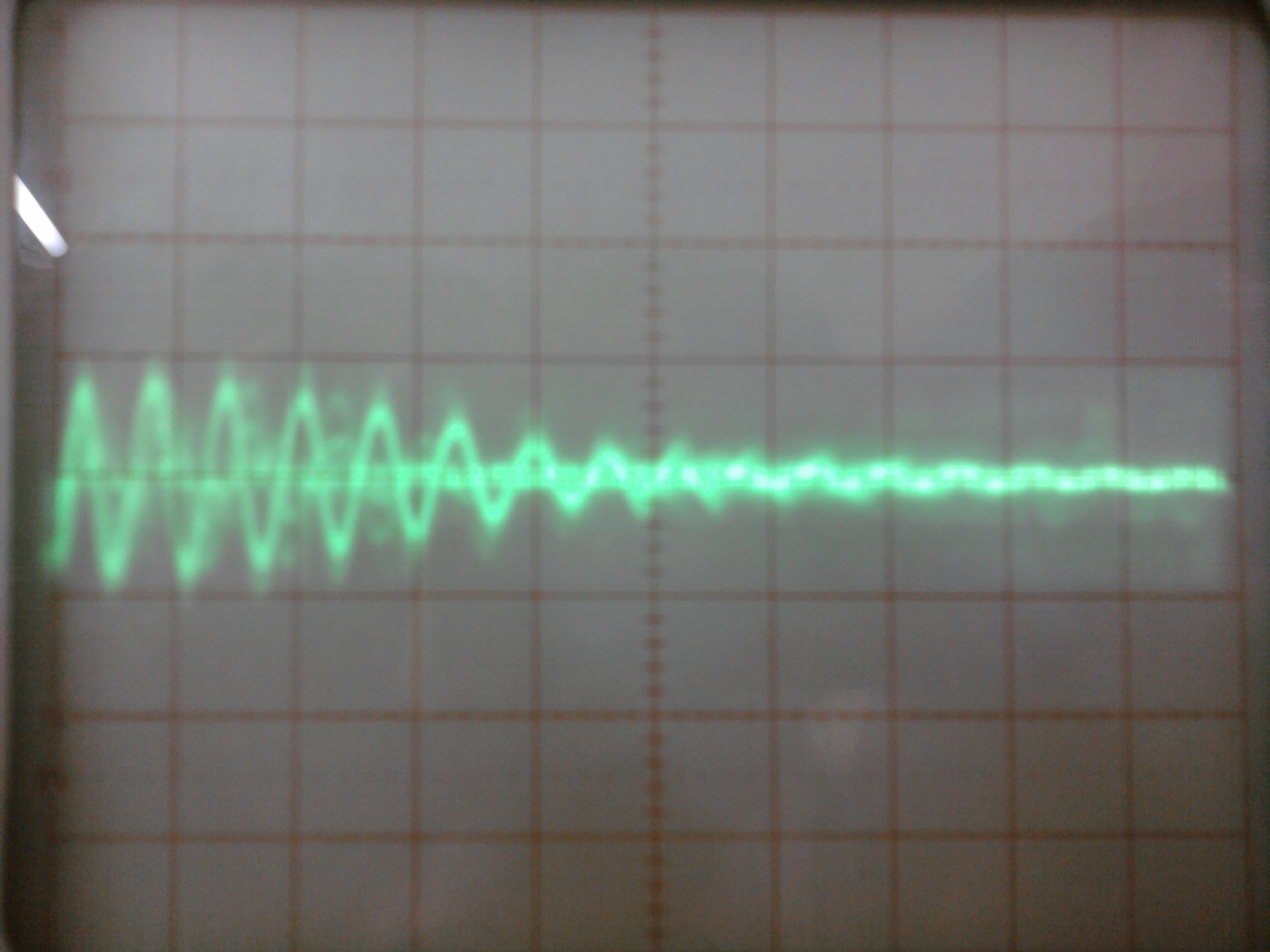
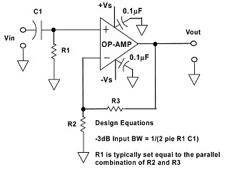
in above ckt these are values.

C1=150uF

R1=10k

R2,R3=20k 

VS=12 and -12v,  

Vin has a Accelerometer whose output is around 9 Vdc+AC signal. when it is at rest i see 200mv peak to peak noise in the wavefom. but if i replace R1 with 100 and r2,r3 to 200 that noise come down to 10mvpp. what is wrong with above ckt?   

  • Even if we take into account only  the noise of the resistors  which is proportional  to the SQR(4kTR) we will see that  noise performance will be better for the circuit  with less ressistance value.

    Additional information about amplifier  noise analyse you could find in the next articles:

    - http://www.ti.com/lit/an/slva043b/slva043b.pdf

    - http://www.analog.com/static/imported-files/tutorials/MT-047.pdf

  • Abitkin,

    Can you provide more information on the sensor? This may help diagnose the problems.

    You have not described the nature of the noise you are seeing. A description or scope photo would be helpful. My best guess is that the noise is coming from the sensor, not the amplifier. Changing R1 to 100 ohms could very likely be loading the sensor, reducing its output. This would account for the reduction in noise but would not be a cure for the real problem.

    Changing R2 and R3 to 200 ohms is not recommended. This creates a very heavy load for the op amp and there is no value to matching the DC resistance on the inputs of this amplifier because it has internal input bias current cancellation. For an explanation you can refer to this discussion...  http://e2e.ti.com/blogs_/b/thesignal/archive/2012/04/17/internal-input-bias-current-cancellation.aspx. I recommend R2 = R3 = 10k ohms regardless of the value used for R1.

    Regards, Bruce.

  • Bruce, Sorry for not providing complete detail of setup. Yes your guess is absolute correct. noise is at sensor side. Sensor is IEPE accelerometer. I am providing constant current of 2.5ma through LM334 as shown in schematic.

    The accelerometer is http://www.pcb.com/searchresults.asp?searchcriteria=352C33.

     Here i have attached screenshot of waveforms. these waveforms are acquired using NI9234 (24bit Analog input card) with 25ks/s and for 25k samples. I think LM334 is generating those spikes. what should i do to provide current to accelerometer without those spikes.

    Regards, Abitkin 3240.IEPE.zip

  • Abitkin,

    I agree, it appears that the LM334 is probably producing the waveform you are seeing. I believe it is oscillating or not operating properly. This may be because the accelerometer load is too high a resistance for the current source to operate properly on three cells. The specifications on the accelerometer are ambiguous and confusing so I cannot be sure of this.

    I recommend increasing the supply voltage to the LM334 with a variable power supply. You can increase gradually to 15V, or so, to see if the oscillation stops. Assuming the LM334 is not damaged, the current will remain limited to 2.5mA. If you have doubts about the condition of the LM334, you can test it driving a current meter and vary the supply voltage to assure it is limiting properly at 2.5mA as the voltage is varied.

    Regards, Bruce

  • Hi abitkin,

    Is the "at Sensor" photo DC coupled? If so, there is only a 5mV DC across the sensor - that is not enough to run the sensor.

    You may not be biasing the sensor with enough voltage. The datasheet has power specs on page 13 (tilt your head sideways):

     http://www.pcb.com/techsupport/tech_force.php

    It shows the output bias voltage as 7-12V - which makes me think that the output should be floating around 7-12 V when biased with >2mA. 3.5V may not be enough to power the internal amplifier.

    Have you tried increasing the sensor supply voltage above 4.5V? The LM334 needs about 1V across it to operate...and the whole LM334 circuit+sensor may not be fully functional yet and could be "chirping" in and out of operation.

    The standard shows a minimum of 4V for the sensor. The LM334 will needs >1V across it to function.

     http://www.mmf.de/iepe_standard.htm

    One of your photos is "with constant R330" - I assume this is replacing the sensor with a 330 ohm resistor. What happens if you replace the LM334 circuit with a ~750 to 1K ohm resistor with the sensor connected? If the LM334 is the source of the noise, it should go away.

    Is this circuit fully shielded? If the LM334 or the sensor are not functioning, the entire input line is high-impedance and will easily pick-up 60/120 Hz line noise (or whatever noise) is floating around the circuit.

    What does the output look like on a "real" scope? Can you speed up the samples to see what the waveform really looks like? What is the center terminal voltage on the sensor coax when connected to the ni9234?

    Regards,

  • Hi Paul,

    Sorry again for being not able to provide full detail.

    Paul Grohe said:
    Is the "at Sensor" photo DC coupled


    No sensor is AC coupled. (NI 9234 has option to chose AC or DC couling). All Waveforms are AC coupled.

    Paul Grohe said:
    It shows the output bias voltage as 7-12V - which makes me think that the output should be floating around 7-12 V when biased with >2mA.

    I am using the three ~9VDC alkaline batteries in series to get around 24VDC  (i forgot "9v'" in previous post, but that i had mentioned in schematics). So i am providing enough power to sensor excitation. The output is floating around 9 VDC as i said in my first post. 

    Paul Grohe said:
    What happens if you replace the LM334 circuit with a ~750 to 1K ohm resistor with the sensor connected?

    Well there ls little improvement in signal (Noise spikes value is little less) when i put 1k resistor. but may be this is because sensor's output  impedance is a 250ohm so signal is losing 1/4 signal strength (Please correct me if i am wrong)

    What i have observed when putting constant R without connecting sensor  is that as R increases the spikes  amplitude is also increases. I have tried from 330 to 20k resistors.

    I have tested sensor directly connected to ni9234 (ni9234 has option to provide IEPE excitation) that photo is "with ni IEPE" . so sensor is working(it is also responding to vibration) . I had measure the current while changing R as said above. its constant 2.5 ma so LM334 is also working fine. 

    Paul Grohe said:
    Is this circuit fully shielded?

    No, it is not shielded. I have made this circuit on GPB and terminal connectors. I had never thought about line noise(60/120 Hz). So i will do proper shielding and will enclose this in shielded box.

    Paul Grohe said:
    What does the output look like on a "real" scope?

    I have analog scope. Photos from that scope were not worth to upload. (Quality of photos are bad, not the scope) so i had captured waveform with NI9234  

  • Hi Abitkin,

    The fact that the "spikes" are still there when you replace the LM334 circuit pretty much rules it out as the noise source.

    I think you are seeing power line noise pickup. 5mVp-p of noise is not uncommon.

    At 50K samples over 1 second, that's 20ms/sample. 60Hz is 16.6ms - so I think you are seeing an aliasing of the 60Hz/120Hz noise as the "spikes". Speed up your sample rate to see what the actual waveform look like. Otherwise, use the analog scope to see what is happening.

    Your circuit has an impedance of about 250 ohms (dominated by the sensor output impedance). That is high enough to be able to "pick up" noise by any unshielded wires.

    So a few more questions.suggestions:

    1. Is the sensor cable coax? How long is it? What kind of coax? (Sorry, I have to ask...).

    2. Is the sensor grounded to anything else? It could be a classic ground loop...

    3. Is the sensor or coax near any motors or transformers? Fluorescent lights? CRT monitors? Does moving the circuit change the noise?

    4. Is there a large bypass cap across the battery? Battery impedance falls rapidly over frequency.

    5. Are the batteries shielded?

    6. Use a single-point ground. The critical "reference" ground on the amplifier is the ground side of R3. All the grounds should return to this point.

    7. Add 10uF or larger supply bypass caps on the amplifier supplies. Is the amplifier powered from a lab supply or batteries? If lab supply, make sure chassis ground link is disconnected so that circuit ground and "green" earth ground are not tied together.

    8. Try putting the whole circuit in a grounded enclosure (coffee can, paint can, metal trash can, large cookie tin) and see if the noise diminishes or goes away.

    Try using a digital camera (w/o flash) or your camera-phone and take a picture of the analog scope (be sure to note time/div settings and ground reference point) and send it to us so we can see what is really happening. If we can see the actual waveform, we could probably tell you exactly what is happening....

    Regards,

  • Hi Paul,

    Turing off  one of the UPS for computer in lab greatly reduce the noise, now when i put resistor as a load for LM334  i don't see any noise. But when i connect sensor, noise appears as shown in below images. Now GPB  is into the shielded box,  those are some of images with sensor connected .


    Horizontal  deflection 0.2 us/div,  vertical deflection 50mv/div

    Horizontal  deflection 2 ms/div,  vertical deflection 50mv/div

    Paul Grohe said:
    1. Is the sensor cable coax? How long is it? What kind of coax?

    yes, its length is around 3 meters. It's two core shielded cable.

    2. sensor is not grounded to anything else.

    3. Yes sensor is mounted on motor, where it supposed to measure vibration. but  these measurements are taken when motor was off.

    4.  no

    5. yes . i have put the whole circuit and batteries inside aluminum box and connected circuit ground to the body of box.

    6. Sorry for not being clear. Being ruled out OP07 as a noise source i am not considering that part of circuit for debugging now. all measurements are taken directly from sensor through AC coupled scope.

    Regards, 

    Abitkin