This thread has been locked.

If you have a related question, please click the "Ask a related question" button in the top right corner. The newly created question will be automatically linked to this question.

XTR117 to MCU interface

Guru 22270 points
Other Parts Discussed in Thread: XTR117, XTR111

Hello,

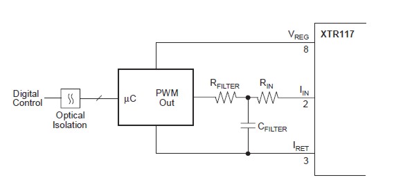
I want to interface the XTR117 to a standard 3.3V MCU  pin with PWM.  In the datasheet it has examples of digital control.  I am a little confused about what digital control means here.  My understanding would be that the MCU was the digital control and for the diagram below I would have thought that the opto-isolator would go between the uC and the Rfilter.

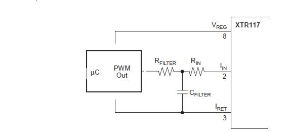
Can I connect the PWM output of my MCU to the filter directly without an opto-isolator as in the last diagram?


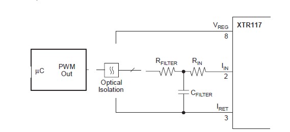
This is my understanding of Digital Control.

This is ideally what I want to do.  The XTR117 is so small that I don't want to waste time soldering it or building a circuit board just to test it.  The end use is just a demo for testing.  It is a last minute addition to a prototype and the box is already crammed full!!!

Thanks,

  • Hello,

    Your final diagram will work fine as long as the uC in your diagram is powered from the XTR117 VREG pin and the GND of the uC is connected to ONLY the XTR117 IRET pin.  The XTR117 is a 2-wire transmitter and the entire sensor, input, and control circuitry must float above the IRET pin so that when the output current of the XTR changes the sensor and input circuitry biasing and other voltages do not change.  Therefore if a uC is added to the 2-wire loop then it and all of its communication voltages must also float with the XTR supplies.  This doesn't pose a problem for communicating to another other device that is also powered between the XTR VREG and IRET, but any device powered to a "system" Power and GND will not be able to communicate with the uC without some type of isolation based voltage level shifting.  The optocoupler is shown to provide this isolation based level shifting because if the microcontroller needs input from another controller or device in the system that is not part of the remote 2-wire loop then the communication must be isolated so that the signals going to the XTR117 uC are able to float with the XTR VREG and IRET. 

    I'm not sure what you're looking for based on the limited description of your final application.  If you want a current output driving IC that is controlled by a micro controller that also interfaces with other devices in the system that are powered from a system supply and GND, then you may want to consider a 3-wire transmitter such as the XTR111.  The XTR111 is a 3-wire transmitter and the input circuitry does not have to float and is much easier to interface with a controller without the need for isolation.

    Hope this helps.

    Best Regards,
    Collin Wells
    Precision Linear Applications

  • Thanks Collin for the explanation.

    In the Data sheet they don't seem to give any explanation at all about the digital interface.  You should get them to include your description in the next REV.

    I should have thought of it as something similar to a MOSFET high side driver.  The ground floats while the gate to source voltage remains constant as the voltage changes.

    The XTR111 appears to be the best option and better pricing.

    Thanks again.

  • I should be able to use second diagram for my application, using +5 Vreg from the XTR117 for the opto-isolator, correct?

  • Hello Greenja,

    Yes, the concept is very similar to the MOSFET driving circuit you mention. 

    It seems you're back on the XTR117.  Have you decided that you do need a 2-wire transmitter?  If you provide more information about your application I can probably help more. 

    If you're using the XTR117 then the second diagram should work fine.  Bias the driving side of the opto-coupler to the control circuitry voltage potentials and power the receiving side only between the XTR VREG and IRET signals, basically the same connections shown for the DAC.

    Best Regards,
    Collin Wells
    Precision Linear Applications

  • Hello Collin,

    The component count and ease of implementation and time restraint made me reconsider the XTR117.

    The XTR111 should be arriving in a couple of hours actually and since it has the output error flag I'll probably use it.

    Believe it or not, but I have never had to use 4-20mA in any mcu, or PLC application in over 10 years!  I still don't, this is just to demonstrate that a 4-20mA output is available.  My time researching 2 wire and 3 wire loops may be in vain.

    For the XTR111 the 3.3V mcu has a DAC. I have the following questions:

    1.  Do I still need to set the Vreg to 3.3V using R1 3.3kand R2 Ω 33kΩ even though I will not be using it?

    2. Can I connect the DAC directly to the Vin or is Rs required?

    3. I want to have a 0 to 20 mA output as in fig.47 would I need to put in a 3.3V reference diode or would setting the Vreg to 3.3V be enough?

    4. Where are the calculations for figure 47 if I want to use other voltages?

    Thanks,

  • Hello Greenja,

    Thanks for the additional information.

    1.)  No, information about the VREG regulator can be found on page 18 of the datasheet.  There are two options when not using the VREG output and are described in the text and shown in Figure 45.

    2.)  Rs is not required.  Unlike some of our XTR devices that require a current input, the XTR111 requires only a voltage input.  The "VIN" input of the XTR111 is the positive input of an amplifier so it is a very high-impedance node, perhaps the 2.5k resistor was shown for some basic current limiting if an over-voltage condition happened on the DAC output.

    3.)  You could use either option, but since the XTR111 includes the VREG I would suggest using it instead of adding an additional component.  If a high precision is required in your system then you may want to consider using a dedicated reference such as the REF3040 or other members of the REF30xx or REF50xx families. 

    4.)  There is actually an error in Figure 44 of the datasheet, the value of the reference resistor should have been 98000, not 120,000.  The values in figure 47 are correct.  There are a few important equations, they are listed below:

    Variables:

    Vref:  Reference voltage supplied to the reference resistor (4.096 in Figure 47)

    Rref:  Resistor between the Vref voltage source and the SET pin of the XTR111 (817.2 kOhms in Figure 47)

    Rset:  Resistor between the SET pin of the XTR111 and GND (2 kOhms in Figure 47)

    Voffset:  Desired input voltage to produce a 0A output current from the XTR111

    Ioffset:  Offset current required to cancel the offset voltage so the XTR111 has a 0A output.

    Ioutmax:  Maximum output current.  In a 4-20mA system Ioutmax = 20mA.

    Calculation for the resistor between the reference voltage and the SET pin:

    Ioffset = Voffset / Rset

    Rref = (Vref - Voffset) / Ioffset

    Calculation for input voltage required to produce the desired maximum output current, Ioutmax

    Vin = (10*Rset*Vref + Iout*Rref*Rset) / (10*Rref + 10*Rset)

    I've included an image of a MathCAD file I use to calculate these values because it may be easier to read:

    Regards,
    Collin Wells
    Precision Linear

  • Excellent response Collin.

    I will post my result after testing.

    Thanks,