This thread has been locked.

If you have a related question, please click the "Ask a related question" button in the top right corner. The newly created question will be automatically linked to this question.

optimized amplification circuit for ultrasonic sensors

Other Parts Discussed in Thread: TLV3501, OPA320, TLV2352, OPA37

Hi

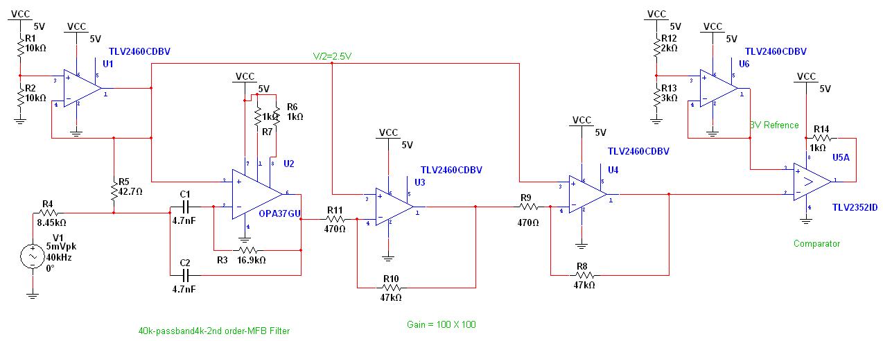
   I need to design a ultrasonic sensor configuration where a transmitter and a receiver are placed face to face. In response to a transmitted pulse of sensor resonant frequency, receiver will generate a signal. I have to measure the time the received signal cross a specified threshold with as much accuracy as possible. Prposed receiver configuration consist of a active 40k Fc - 1k pass band - bandpass filter, followed by a gain(1000) amplifier. This is followed by a comparator with voltage threshold specified by a ref. voltage ic.

I would like to have following clarification. As per filterpro tool design GBW of amplifier used in active filter should be 160 MHz. will a 20MHz GBW amplifier suffice???

What is desirable -- a multi stage gain stage or a single stage using high GBW amplifier. What are the pro and cons involved?

I would like to have few suggestion regarding a high speed comparator with very fast switching time.

Ajit

  • Hello Ajit,

    Sounds like a neat project.  I worked on a robotics project in college where we used an array of four hydrophones to detect a sonar beacon and dock with it.  We had to very accurately detect when the sonar signal reached each hydrophone so we could use time-of-arrival math to determine the trajectory of the beacon based on our last reading, so it was very similar to what you're trying to do.   

    That said, there are several posts on the forum already devoted to hydrophone, geophone, and microphone applications which are all very similar.  Please consider searching the forum for some other posts like the one below for ideas:

    http://e2e.ti.com/support/amplifiers/precision_amplifiers/f/14/p/166388/607712.aspx#607712

    http://e2e.ti.com/support/amplifiers/precision_amplifiers/f/14/t/161153.aspx

    Regarding the filter-pro results, I'm not sure what you designed but to require a 160MHz amplifier you must have a pretty complicated or advanced design.  The circuit will not properly function if you do not use an amplifier with appropriate GBW, so the 20MHz amplifier will not work for your current circuit.  I would suggest increasing the number of stages, or the order of filter, or gain in the filter to lower the GBW requirements.

    It is always desirable to front-load the gain in a sensor system because this will maximize the SNR of the system.  However if your gain requirements are too great and result in excess noise that swamps out the sensor signal then you may have to spread the gain across a few stages.

    For a high-speed comparator, check out the TLV3501.

    Best Regards,
    Collin Wells
    Precision Linear Applications


  • Hello everyone

       Thank you Collin for your prompt reply. For above application I am trying to evaluate some alternatives. Overall objective of analysis is to reduce the variability in the time measured. At present it is about 100 ns. For my application it should 20-40ns or less.  Basic signal processing chain is:

    Filter Specification: 40KHz , pass band width 1KHz, Cheby 1, MFB

    1)I would like to know whether i should distribute the gain between filter and next amplification stage?

    2)What should be the order of the filter? There aren't any major noise source in the environment where the application would be used. 50Hz off course would be there when I am experimenting in lab but smt component based board with short traces i hope will reduce it. So noise added due to different component would be a major consideration. 

    2)The GBW that i was talking about is of the op-amp used in the active 40KHz band pass filter. As per Filterpro it should be 160 MHz. So i would like to know whether OPA320 would suffice? Is there any better alternative?

    3)How appropriate it would be to use a Instrumentation Amp. Instead of OPA320?

    4)A comparator output would be used to stop a digital counter in FPGA which is counting the time elapsed. Will it be better not to use the comparator at all? as There is also a 0 to 1 detector circuit at the FPGA i/o pin.

    expecting some insight and use full suggestions.

    regards

    Ajit Singh

  • Hi Ajit,

    Unfortunately the image of your signal processing chain did not come through.  Would you please try inserting it as a file instead of an image?  I have a few other items I need to close out but will be working this issue after and will reply back as soon as I can.


    Regards,
    Collin Wells
    Precision Linear Applications

  • hello Colin

           Please find attached updated signal processing chain. GBW of OPAMP is affecting filter response. So Instead of OPA320(GBW - 20 MHz) i have used OPA37(GBW-63 MHz). Instead of TLV2352 Comparator i will be using TLV3501, but it wasn't there in multisim library. I would like to reduce the no of stages.  So for amplification if i use an Instrumentation amplifier will it going to be better? Also if I directly connect amplifier output to FPGA I/O pin, what problem may arise.  

    regards

    Ajit

  • Hi Ajit,

    There's probably not much to gain here by using an instrumentation amplifier unless it is used as the first stage which probably isn't necessary.  Instrumentation amplifiers have the advantage of very high input impedance and CMRR and although both would be good, I'm not sure either of those will be necessary to achieve the opertion you're looking for.  The only way I see to reduce stages would be to include gain in the filter stage which may push the requirements of the GBW of the OPA even higher than previously prescribed by FilterPRO. 

    The trouble of connecting the output of an amplifier directly to a digital signal is that the output is not a "1" or "0", it's every signal in between.  The result is that when the OPA output is not at one rail or the other it will be placing the input circuitry of your FPGA in a potentially unknown state.  The comparator prevents this from happening because the comparator output is either always one rail or the other and not voltages between the rails.

    Regards,
    Collin Wells
    Precision Linear Applications