This thread has been locked.

If you have a related question, please click the "Ask a related question" button in the top right corner. The newly created question will be automatically linked to this question.

photodiode AC amplifier

Other Parts Discussed in Thread: OPA380, IVC102, OPA320, TLC2274, LT1014

Hi,

I am trying to build a portable infrared reflection analysis device, capable of identifying different reflectivity surfaces located a couple of cms in front of a IR Led and photodiode.
In order to avoid interference (sun or bulb light), I am generating an AC signal of 35kHz from the LED and trying to measure the light reflected with the photodiode.

I have read that the photovoltaic configuration is more suitable for slower but where more precision is required (low noise). Moreover, the photovoltaic configuration consumes less power and is linear, however I tried to run different topologies without any good results even on DC drive of the LED (Ex. figure 2 of document focus.ti.com/lit/an/sboa061/sboa061.pdf)
The only configuration that seems to work in the simulation and protoboard is the transimpedance amplifier with the photodiode in Conductive Mode for DC and AC.
My LED is Everlight IR204 and the photodiode is Everlight PD438B.

Any help or suggestion will be appreciated!

Different topics I read:
http://e2e.ti.com/support/amplifiers/precision_amplifiers/f/14/p/182579/658369.aspx
http://e2e.ti.com/support/amplifiers/precision_amplifiers/f/14/t/96946.aspx
http://e2e.ti.com/support/amplifiers/precision_amplifiers/f/14/t/167369.aspx
Thank you!

  • Roberto,

    Photoconductive mode generally must be used to get good frequency response. A transimpedance amplifier holds the voltage on the diode constant and therefore does not charge and discharge the diode capacitance.

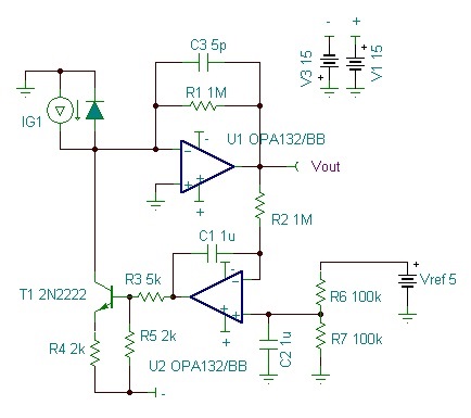
    Based on the information you have provided, I believe the circuitry in the following post would be most likely to meet your needs:

    http://e2e.ti.com/support/amplifiers/precision_amplifiers/f/14/p/182579/658369.aspx

    The two-op-amp loop to remove the constant light component would seem to make sense in your application.

    Regards, Bruce.

  • Dear Bruce,

    Thank you very much for your comments and reply.

    The circuit seems to be very appropriate for my application, but although it worked in a simulation (Tina), I haven't been able to make it work on the protoboard. I am not sure if the photodiode model I used in the simulation is different from the one that I am using. I will keep trying today...

    On the other hand, what do you think about using directly transimpedance amplifiers? I have seen them in Pulse Oximeter designs (as described in the Medical Applications Guide, p47 http://www.ti.com/litv/pdf/slyb108e). Specifically:

    OPA380 Precision, High-Speed Transimpedance Amplifier, or
    IVC102U Precision Switched Integrator Transimpedance Amplifier

    Thanks again!!
    Roberto

  • Roberto,

    The OPA380 and IVC102 would not seem particularly suited to your application. The OPA380 is effective at achieving accuracy at low light levels with its auto-zero technique--not important in your application. The IVC102 integrates the input signal. This is great for averaging (accumulating) output over a period. You are trying to extract an AC signal. This would require very fast integration and sampling at at least 2x your modulation frequency.

    You were not specific in your description of problems with the two-op-amp loop that subtracts the average level. If you can provide details, perhaps I can help.

    Regards, Bruce.

  • Thank you very much Bruce.

    Bruce Trump said:

    The OPA380 and IVC102 would not seem particularly suited to your application. The OPA380 is effective at achieving accuracy at low light levels with its auto-zero technique--not important in your application.

    Although the received signal from the reflection is weak, I hadn't realised that the transimpedance configuration with the OPA380 was aimed for low light levels.

    Bruce Trump said:

    You were not specific in your description of problems with the two-op-amp loop that subtracts the average level. If you can provide details, perhaps I can help.

    I don't have the OPA320, so I am using the TLC2274 while I get the OPA320 (10 days). The simulation with the TLC2274 and the AC signal 3kHz works fine. But I haven't been able to get the design working in a protoboard. Maybe the photodiode I am using is different from the simulated model, and I don't have all specs from my IR photodiode (is a cheap one).

    I reduced the feedback resistance R1 to 220k. And I only start to get some AC signal if I use a larger resistance R4 between the T1 emisor and ground of about 50k, however with these values Vout is not hold at an average voltage of 2.5V and instead is almost at 5V.

    Regards,
    Roberto

  • Dear Bruce,

    I have not been able to get the circuit working properly. I am more convinced that the problem is that I don't know my photodiode specs, so the Tina model is different from the actual circuit.

    However, I would like to make sure I am not missing the point, and that the proposed circuit is appropriate for achieving my goal.

    1. What I would like to achieve is to detect small changes in the reflectivity of a surface in front of the photodiode (2cms). For example the differences between a card gray 20% and another card gray 40%. A complete change of surface may take between 100ms to 500ms. I would like to detect the shape of the change and how long a surface is placed on front of the photodiode.

    2. I am using an IR LED and Photodetector because the light must be invisible to human eye. These elements are placed in paralell, pointing in the same direction, and I am trying to distinguish a different reflectivity depending on the amount of IR light that goes out of the LED and comes back to the photodiode.

    3. The main challenges are:
    a) the LED radiant intensity is limited to 4,4 mW/cm2 for safety reasons;
    b) there are different sources of interference such as light from bulbs (50Hz) and from the sun; and
    c) there are some mechanical vibrations in the ambient

    3. The photodiode I am using is is Everlight PD438B (datasheet attached), but I can change the LED and Photodiode. Moreover, the final design should have surface mount LED and photodiodes.

    4. Depending what card I would like to detect, the current induced in the photodiode is approximately 200nA different

    5. Because I don't care the reference level, only changes in reflectivity, I decided to modulate the LED signal in order to be able to filter out the interference (sun and bulb light) received in the photodiode. Then I am planning to rectify the signal in order to quantify the average reflectivity level.

    Hopefully, these details help to understand better my problem and confirm if your proposed circuit design is still the suggested one. In that case, I will keep trying with it.

    Thanks, Roberto

  • Roberto,

    From what I can understand of your application, I think the recommended circuit is well suited. I have inserted the reference circuit below so that we can refer to circuit values and voltages. You have not been very specific in describing what is "not working" in the circuit. Can you provide a diagram of the circuit you have implemented with circuit values and supply voltages. Probe the critical nodes and give me a sense of what is not working. Are the op amp in their linear range. Are voltages as expected?

    I doubt that lacking an accurate model of the photodiode is the problem. I think there is something more fundamental wrong with your implementation.

    Regards, Bruce.

  • Thanks again Bruce.

    Below I am attaching a picture of the circuit I am using, which is your adaptation to single supply with minor changes:
    R4 10k (instead of 2,2k)
    R1 220k (instead of 1M)
    C2 47p (instead of 5p)

    In addition, I added actual measured voltages in some nodes to illustrate circuit behaviour. If R4=2,2k, there isn't oscilation anywhere. If R4=10k, there isn't any oscilation withouth significant reflected light back to the photodiode. But increasing reflected light, suddenly produces oscilation in both U1 and U2 inverting inputs (as shown in the measured voltage). However, the beahaviour is different from the simulation, and there isn't measurable oscilation in Vout.

    Hope this helps you to understand what's wrong with my implementation.

    Thank you very much,
    Roberto

  • Roberto,

    I'm traveling and cannot devote full attention to this right now. I have made a quick check including simulation with your circuit values and op amp. I see no problems.

    I'm not sure I understand a few of your notes. You indicate a 1.3kHz square wave at the photodiode. Is this your modulation frequency? What is the frequency of the unwanted oscillation?

    Do you have good bypass capacitors on the supply pins? How is the 2.5V offset derived? Are there bypass caps on these nodes.

    I'll look in more detail this weekend but answers to these questions will help.

    Regards, Bruce.

  • Dear Bruce,

    Thanks again for your attention!

    Bruce Trump said:
    I'm not sure I understand a few of your notes. You indicate a 1.3kHz square wave at the photodiode. Is this your modulation frequency? What is the frequency of the unwanted oscillation?

    Exactly. 1.3kHz is the modulation frequency of the square wave that feeds the LED. This light is reflected back to the photodiode. The frequency of the unwanted oscilation is 50Hz from lightbulbs and DC sunlight which I am testing now. Also, I would like to be sure not to have problems with other frequencies such as 60Hz in other countries or other type of common interference in the workplace.

    Bruce Trump said:
    Do you have good bypass capacitors on the supply pins? How is the 2.5V offset derived? Are there bypass caps on these nodes.

    I am not sure what you mean about "good bypass capacitors". I am using a 0.1uf capacitor in parallel with the voltage source. Is this what you are asking? What should I take for "good"? In addition, I derived the 2.5V offset as shown here:

    Thanks Bruce and I hope you are having a good trip.

    Regards,
    Roberto

  • Roberto,

    The 50Hz signal you are seeing is apparently not an oscillation but an interfering signal. It might be from the ambient light sources, as you say. Try duplicating the signal conditions with a test “ambient light” solely from sunlight or DC-powered incandescent light. This will have no 50Hz content. Also, ambient “50Hz” light is more likely to have a 100Hz frequency.

    Ambient light rejection can be greatly improved with an optical filter on the photodiode. Try using the dark plastic cover on the front of a salvaged IR remote control.

    You may have interference from poor power supply filtering or grounding techniques. Temporary battery power may help identify this source. Due to the way various points are biased you may have high sensitivity to noise on the power supply.

    Some suggestions for optimization:  Change R5 to 3.3k. Leave R3=5k. Do not adjust these values.

    R4 sets the current range over which the nulling loop operates. With R4=10k, the loop can null a maximum of approximately 150uA of photodiode current from ambient light. Check the output of the nulling op amp, U2, with maximum ambient light. If the output voltage is near the 5V rail, reduce the value of R4 to produce more nulling current. If the output of U2 is less than 1V with maximum ambient light, increase the value of R4.

    The speed of the nulling loop affects the rejection of 50Hz light sources. For R4=10k, C1 should be reduced to 1nF for improved rejection. If you reduce R4, C1 should be proportionally increased.

    If you still have problems with 50Hz light rejection, consider moving the modulation frequency up to 10kHz. Then reduce C1 by a factor of 10.

    I hope these suggestions help.

    Regards, Bruce.

  • Dear Bruce,

    Thanks for your comments and suggestions. I am trying to improve as you suggest including the old remote dark cover, but I have a more fundamental doubt that I would like to clear before trying to optimize the circuit.

    If I put a bright surface in front of the LED and reflect back to the photodiode a large amount of IR light, I get (2500mV DC + 2500mV sq) at the photodiode output. So, is it right to get (3100mV DC + 10mV sq) at U1 output? In the simulated circuit, a low sq voltage at the photodiode output (4mV) produces an big volgage at U1 output (400mV). Moreover, DC component does not rise from 2,5V to 3,1V.

    Is this behaviour expected with the proposed circuit?

    Regards,
    Roberto

  • Roberto,

    I cannot explain the large square wave voltage you are seeing on the photodiode. I don't know how you are probing this node but I could be very sensitive and you may be disturbing normal operation by probing it. I recommend that you probe the outputs of U1 and U2. If the behavior looks as I described it, don't probe at the inverting input of U1.

    Gradually increase "DC" ambient light as previously described without IR modulation. You should see U2 output gradually increase and U2 remain at 2.5V. When U2 reaches 5V, the output of U1 will begin increasing. This is the end of the range of the nulling loop.

    Regards, Bruce. 

  • Dear Bruce,

    Thanks for the guidance. I think I was able to get to the source of my problems by following your comments.

    I did the test you suggested, but the U2 output (3,1V DC) didn't change with variations of R4 (1k - 30k) nor with variations of DC ambient light. So, I used another Opamp that I had at hand (LT1014), and it worked better. With maximum DC ambient light, the maximum value of R4 was 4,7k before U2 output reached 5V.

    Apparently, the main issue was not having the OPA320 so I will get this before any further tests.

    Lastly, I would like to ask what do you think of adding a synchronous detection circuit for the next stage using for example the OPA675. As I will have a square wave plus 2,5V DC at U1 output, but I would need a single number representing the level of reflected light, I was thinking in demodulation using synchronous detection followed by a low pass.

    Thank you very much for your support and guidance on this project.

    Kind regards,
    Roberto

  • Roberto,

    A synchronous detector is the ideal way to process the signal.

    You are welcome and best of luck,

    Bruce