This thread has been locked.

If you have a related question, please click the "Ask a related question" button in the top right corner. The newly created question will be automatically linked to this question.

What to do with unused comperators of LMV7272...

Other Parts Discussed in Thread: LMV7272, TLV3702, LMV339

Hi TI Analog Support Team,

Reading datasheet for lmv7272.pdf it's stated that "All pins of any unused comparators should be tied to the negative supply."

Just asking to be 100% sure: Does this mean both input and output pins even though lmv7272 has a push-pull output stage?

Can you please clarify? Best regards and thanks in advance
  Søren

  • Hello Søren,

    The LMV7272 is a "push-pull" output, so definitely DO NOT ground the output! That is a direct short to V+ if/when the output goes high. Poof!

    Even for "open collector/drain" outputs, we do not recommend grounding the output - just leave it unconnected.

    So just leave the outputs of the comparators unconnected.

    Regards,

  • Hi Paul,

    Thanks for your quick reply. Great that I asked, as it somehow sounded strange and dangerous to me as well, but on the other hand, if output is NC and both inputs are at same potential (GND) what will in this case make sure the comperator isn't oscillating (due to inputs being identical)?

    In my world I would ideally had connected one input to GND and the other to VCC which I find a more "stable state" than the state with both connected to GND? This being said I found the note in the datasheet which gave rise to the original question...

    I hope you can clarify once again - Best regards and thanks
      Søren

  • Hello Søren,

    Yes. If the inputs are connected together, it is possible for the comparator output to "chatter" if the device has a very low offset and the offset crosses through zero due to temperature or power supply changes. I have seen it happen.

    To guarantee that the output will stay in one state, the inputs can be tied to the opposite rails *IF* the absolute maximum ratings allow. To be "legal", the abs max input differential voltage must cover both rails. This will be noted in the Absolute Maximum Ratings section under "Maximum Differential Voltage" or "Differential Input Range".

    In the case of the LMV7272, the abs max "Vin Differential Voltage" spec shows "±Supply voltage" - so it would be okay to tie the inputs to opposite supplies.

    Usually Rail to Rail input comparators can have their inputs ties to opposite supplies, but you still should verify the abs max specifications. And always verify non rail-to-rail input device abs max specifications.

    BTW: The above only applies to comparators - unused op-amp inputs are not designed for large differential voltages and should not be tied to opposite supplies.

    If you are worried about possible noise caused by a "chattering" comparator - then connect the inputs to opposite rails.

    Regards,

  • Hi Paul,

    Thanks again for your feedback with which I fully agree, although it gave rise to last question, as I think I now have two different recommendations? :-)

    1. Tie both to GND (from datasheet)
    2. Tie one ot GND and nother to VCC (from you)

    As such I'm not especially worried about noise as the two GND connection would be connected directly to GND using uVIAs under the chip => No big loop between balls and GND => Most likely no big voltage can appear between balls (but it as well typically only needs to be 300uV for chattering to occour?). The chip will furthermore be decoupled by 100nF on GND/VCC, but will be supplied by a 1V8 IO digital supply connected to lots of (noisy) digital circuitry...

    Good question is now: Which approach would you go for in this case? I think I would go for 2), but that would be "not following the recommendation from the datasheet", which is why I would like to get you input if the datasheet is"wrong" on this? Or if my goodfeeling is "overkill"? Any drawbacks (power consumption?) of going approach 2) as datasheet recommends 1)?

    I hope you can clarify/comment one last time? Best regards and thanks again
      Søren

  • Hello Søren,

    Because this is a Rail to Rail input and Abs Max allows it, you have the option of either tying the inputs together at ground, or, tying the inputs to opposite rails.

    The author of the datasheet chose to mention the grounded input method. This is fairly "boilerplate" and applies to both R-R input and non R-R input devices. Most likely they err'ed on the side of safety as readers may get this stuck in their head and try to apply the split rails technique to other (non R-R input) devices..

    Since this is a "Push Pull" output, there will be supply transients on the supply line when  the output transitions - so random "chattering" could cause noise on the supply line if it was poorly bypassed for high frequencies. The 7272 should be considered a "fast" device since the edge rates are in the nanoseconds - so proper high-speed supply bypassing and layout should be used.

    If you are worried about noise, then I would tie the inputs to the opposite rails to ensure the output never transitions.

    I generally do not like tying signal pins directly to the rail, so if this makes you feel a little uneasy, you can tie the inputs to the rails through 100K series resistors to limit any currents that may flow.

    Hope this clarifies things. It is up to you which route to take. The datasheet is not "wrong", it is just erring on the side of caution.

    Regards,

  • Hi Paul,

    Thanks again for your great and detailed reply. Highly appreciated :-). This being said I'm still not sure what I prefer. Main goals are:

    1. Make sure it won't ever oscillate
    2. PCB board size (which is the reason for selecting the two part BGA version as opposed to a package with just one comperator - which would prevent the problem easily once and for all :-))

    Based on 1) I'm not much of connecting both to GND. Based on 2) I'm not very keen at adding two additional 100K resistors for tying the unused inputs as recommended by you.

    With this in mind - May I ask: Which path would you take? I think to lean most toward datasheet tying both inputs at GND, but I do not feel on secure home ground :-(, as I would like :-)... 

    Best regards and thanks again
      Søren

  • Hello Søren,

    I have to issue a Mia-culpa. The LMV7272 is NOT a CMOS input device - it is a bipolar input device. This changes things slightly. I have edited my previous reply above to remove reference to the CMOS inputs.

    At differential input voltages greater than 7V on a bipolar input device, there may be a risk of "parametric shifts" in the input stage. Steps are taken internally to mitigate this effect to allow Rail-Rail differential inputs - but it is still a possibility to see some very slight input stage degradation (beta degradation) with large differential voltages.

    Your supply voltage is only 1.8V - that is well below the 7V limit and should not be a problem at all.

    Since this channel is unused - it should not matter if the offset changes a bit over time -and the risk is so slight at 1.8V. I spoke to a designer and he did not think there would be any problems.

    So...again...it's up to you. The tradeoff is the risk of occasional offset-dependent "chatter" using the grounded inputs, or, a long term minor degradation of an input stage you will never use to insure the ouptut never "chatters".

    It's tough being an Engineer...so many decisions! :^) But we think it is still okay to pull the inputs to the opposite rails to prevent chatter.

    Regards,

  • Hi Paul,

    Thanks for your great feedback. Sorry for my very late reply on this. I was side tracked on a few other tasks and then the summer arrived, but now I'm back :-)

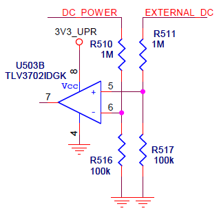
    And I agree - It's all about compromises. I guess the reason I'm so "scared" about connecting both inputs to same potential is as I once by mistake shorted the two signals DC_POWER and EXTERNAL_DC using a 0R resistor (so both nets got the same 12V) on the schematic below, which made the output of the TLV3702 oscillate like crazy (like 2MHz AFAIK).

    As it seems you are more into analog input stages than I am can you explain why this would cause this comparator to go totally bananas? Is it due to the resistors together with a slight change in input current passing through them then when the output changes? Or any other good reason you can easily come up with that would cause this circuit to oscillate like crazy? And secondly: Why wouldn't this problem occur on the device discussed above if both inputs are tied to same potential (GND)? Because of no big resistors in path and/or because of the offset voltage?

    Hoping to learn a little more here - Thanks for all your great comments - They are highly appreciated :-)

    Best regards
      Søren

  • Hi Søren,

    Most likely the offset was low and close to the noise threshold. Every circuit is different so it is hard to say just why your circuit oscillated. Most likely it was either capacitive coupling between the input and output pins - or - glitches through the power supply.

    Comparators draw large currents when the output changes states (up to several mA in several ns), and can "droop" the supply if not properly bypassed.

    Your circuit above has a ~100Kohm input impedance, which could allow the output transients to couple back into the inputs through a few pF of board strays. That's all it takes!

    So if you want to feel safe, ground one input and lift one to a convenient voltage several mV above ground. That voltage could be from a resistor divider or an available reference line.

    If the comparator is a bipolar open-collector comparator (LMV339/393 series), set the output high as to not waste base current in the unused output transistor (save a few uA in supply current).

    Regards,

  • Hi Paul,

    Thanks for your feedback and for "confirming" that the problem of the old circuit potentially could be caused by the 100K resistors together with stray capacities to power supply, as I kind of had the idea as well, but just wasn't 100% able to express :-) I think I learned what I needed for now, and hope other people finding this thread in the future can benefit from your great help and guidance as well...

    Best regards and thanks again - Enjoy your weekend
      Søren