This thread has been locked.

If you have a related question, please click the "Ask a related question" button in the top right corner. The newly created question will be automatically linked to this question.

THS4150

Other Parts Discussed in Thread: THS4150, BUF634

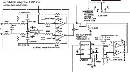
We are putting a signal parallel to the output of the THS4150CD. The output from this signal is 5V for 100 to 500 microseconds. This signal then goes to the BUF634 and finally out to an ADC. Should we have a resistor in this signal to protect the THS4150 chip, or any other precautions that should be taken?

We have purchased over 100 of the chips already, and are ready to order the boards as soon as we find out about this.

  • Hello Mikhail,

    The THS4150 can drive a capacitive load of up to 10pF without stability issues, but for anything above 10pF it is recommended to use a series resistor to provide isolation. The BUF634 has a typical input impedance of 8MΩ || 8pF at room temperature. So in some ideal cases, the circuit should work without the resistor. However, in order to account for varying process and temperature, as well as possible trace capacitances, I would include one. The THS4150 datasheet recommends a minimum value of 20Ω for most applications (page 15).

    Let me know if you have any further questions. Thanks,

    Jason Blackman 

  •  Dear Jason,

    Thank you for your reply.  I have more question for clarification.  We already have a 249 Ohm resistor between the THS4150 output and the BUF634 input. Our question pertains to the 500 microsecond pulse that comes from the TC4427 through a set of relay contacts, that are only closed for this pulse. The TC4427 output is applied to this point to have a bipolar signal that goes through the 249 Ohm resistors to the inputs of the BUF634's, and from there goes to the connector "OUT". The ADC connected to the "OUT" then sees a 5VDC amplitude for this pulse. What we really want to find out is if it possible to directly connect the output of the TC4427 to the output of the THS4150 for the up to 500 microsecond pulse through the relay contacts.

    Thanks again,

    Mikhail

    (608) 262-2339

  • Mikhail,

    Thank you for explaining the issue further, I understand now. The problem that comes into play with directly connecting the TC4427 output to the output of the THS4150 is that those feedback capacitors will get charged up. During the 5V pulse, the caps get charged up to some value, and then when the pulse is gone it will take some time to discharge back to the previous voltage level. This causes a temporary and decreasing DC shift at the output. Here is a TINA schematic I built to simulate this case, which you can play around with:

    5127.THS4150.TSC

    I couldn't quite read what component values you have in your schematic, so they might differ. Running a transient analysis shows what I was describing previously:

    Other than this problem of shifting the output, connecting the output of the amplifier directly to a 5VDC source might draw more current than the THS4150 can handle. In the simulation, the output current seems to max out at about 80mA, but this might be a result of the model and not actual performance.

    Does this help with your question?

    Jason Blackman

  • Dear Jason,

    I am going to check  component values and  play around with your model

    Thanks again,

    Mikhail