This thread has been locked.

If you have a related question, please click the "Ask a related question" button in the top right corner. The newly created question will be automatically linked to this question.

Integrator up to 1MHz

Other Parts Discussed in Thread: LF347, OPA140, OPA132

Hei,

I would like to design my own integrator witch bandwidth go up to 1MHz. I can make basic integrator but that work only farly low frequency. Can somebody help me to give me some site, guide or good book where is showing how to design integrator witch give me 1MHz?

Thank you for advanced. 

  • Kimmo,

    Can you provide a schematic of the circuit you are using? What op amp are you using? How are you judging the performance of the integrator?

    Regards, Bruce.

  • Thanks to help!

    I am using op amp LF357N. I am actually doing Rogowski coil to messure current witch bandwidth go up to 1MHz. Thats why I need make integrator that integrate coils voltage.

    When I simulating that basic integrator that I made one frequency 1MHz, there come quite big offset to output signal. And when I try some faster op amp it didint integrate at all (mayby there is problem this capasitor value or something).

    I would like to have integrator that plot diagram -3 dB point is 1 MHz. If it is quite flat to that point it would be cood.

    I hope this gave you better picture of my situation.

    4645.Integrator.pdf

  • Hi Kimmo

    It looks to me like your DC gain is -33. But your input voltage is 1Vrms. Is this deliberate?

    regards

    Steve

  • Kimmo,

    I believe that you are using an LF347, correct? There is a discrepancy in your posting but your schematic indicates LF347. This device does not have sufficient gain-bandwidth to provide a good integrator response to 1MHz.

    A possible replacement is the OPA140 which has a gain-bandwidth of 11MHz. I suggest changing the value of R2 to 1M-ohm as this will give you flatter response down to the 50Hz range. R3 is unnecessary in this circuit as the input bias current of a FET-input amplifier is very low.

    Regards, Bruce.

  • First; thank you for your help and sorry that this response have been take while, I was on holliday.

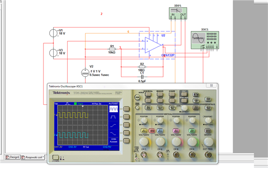
    A make changes on my schema. I didint have that OPA140 in my Multisim but I used OPA132P where have bigger bandwith up to 8 MHz (if I am right...).

    Actually I have been this same problem erlier when I have OPA where I is bigger bandwith then this integrator wont integrate any more. Can you give me some good advise this problem.

    I post my Multisim simulation result in here.

    Thank you very much your help!!!

  • Something is not closing for me in the conceptual area. If it is an integrator, it cannot be flat. It must have a diminishing gain of -20dB/decade.

    You could have a pole, but that one would be at a very low frequency. I don't see the logic of planning an integrator which is flat until 1MHz. It would be an integrator only of very high frequencies, for frequencies lower than 1MHz it would be a linear amplifier.

  • Kimmo,

    I share Albert's concerns. It appears that you have designed an amplfiier with a gain of -100, not an integrator. Bandwidth of this amplifier will be approximately 80kHz due to the gain-bandwidth of the op amp.

    I cannot make sense of the simulation that you have shown as this cannot agree with the circuit you have drawn.

    As Albert has commented, an integrator will have a falling -20dB per decade response. For a Rogowski coil, I would think you would want this falling response to start in the 30Hz region. From your original question, I assumed that you would want this integrator response to continue to 1MHz.

    Regards, Bruce.

  • I have one Rogowski coil (made of firm) wich bandwidth start 80 Hz and continue 16 MHz. Becouse those are fairly expensive I would like to make my own rogowski coil not so accuracy measure but still curren waves are not totally wrong.

    I have title bit promblem to undestand every detail of this integrator and opa because I am electrical engineer and I am not familier of this topic (still I am keen to learn!!)

    I have use this web page to desing of my integrator

    http://freecircuitdiagram.com/2009/05/03/integrator-circuit-with-reset/

    http://en.wikipedia.org/wiki/File:Rogowsky_coil.png

    I hope that you would like to help me litle more still I am beginner of this thing.

    Right now I dont have on my mind any specific gain or that kind of thing. I want to first make this work 80 Hz...1MHz (12,5 ms ... 1us). I simulated this integrator that way that I put input square wave wich frequency are 80 Hz and 1 MHz and check if output is triangle wave (is this right thing to do?).

    What is your recommend of this C1 R1 and opa. I try to look but my multisim didint have that OPA140 :( is there any alternative OPA.

    Thank you for your help!

  • Kimmo,

    Here is a possible circuit for your consideration. It behaves as a good integrator from approximately 50Hz to over 1MHz. The OPA140 is shown but the OPA132 would also work well. The response in the 1MHz region would not be quite as good as the OPA140.

    Regards, Bruce.

  • hi bruce,

    can you let me know whether you included delay time for the integrator to capture the signal from coil and process it..?