This thread has been locked.

If you have a related question, please click the "Ask a related question" button in the top right corner. The newly created question will be automatically linked to this question.

LMH6515 Problems

Other Parts Discussed in Thread: LMH6515, THS4304

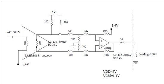
I build up a schematic with LMH6515 as VGA shown below.

The opamp in this figure is THS4304.  LMH6515 Pin13 is connectted to Pin16, so that its output impedance is 200ohm.

When I measured this design, I got lots of problem.

1.  VGA(LMH6515) output pins has different DC level. Pin 15 is 2.1V, and Pin 14 is 2.5V, however, they are designed to be 2.8V.

2.  The VGA seems have a dynamic range around 50dB. The input signal is 50MHz.

Input power -20dBm
Output Power
Gain Code  Designed Measured
00000 -44dBm -59.87dBm
00001 -43dBm -58.72dBm
00010 -42dBm -50.61dBm
00100 -40dBm -48.81dBm
01000 -36dBm -36.63dBm
10000 -28dBm -26.46dBm
11000 -20dBm -16.99dBm
11100 -16dBm -12.79dBm
11110 -14dBm -10.73dBm
11111 -13dBm -9.52dBm

3. When the Gain code is set to 111xx, I got lots of spurs. The max one is at 73.7MHz.

4. Even I shut down input signal, I also got spurs.

Does that mean the VGA is unstable? If yes, any suggesttion for the schematic/PCB design?

  • Why the schemaitc is invisible?

  • Hi,

    The tail current in Figure 2, shown below, is ~40mA which should result in an expected 2.8V with the schematic you've shown, as you have noted.

    Vout = (5V/100 - 20mA) / (1/1.4k + 1/100)= 2.8V

    You don't show how you drive the two input pins. Please make sure they are impedance matched (ideally both AC coupled with equal impedances).

    Please check to make sure that the input differential voltage is in fact 0V when reading the voltages of 2.1V and 2.5V on output pins. You may have a DC differential input?

    I did not run through your Measured vs. Designed gain table because I was not sure where your input / output reference points were? I suspect you're measuring at the output of the THS4304. I do find the resistor values you've chosen around the THS4304 to be rather high (10k) for 50MHz operation! With 10k and only 1pF of parasitic capacitance, you'd roll-off your frequency response to about 16MHz! So, I suggest lowering / scaling your resistor values lower for higher speed.

    The spectrum analyzer plot that you supplied with input signal removed still shows the sharp spur which is probably indicative of instability. I recommend you keep your external components tightly close to the output pin to avoid parasitic capacitance. Also, avoid long traces and use small surface mount components. If all else fails, get the LMH6515 Evaluation board and use it as a guide.

    Hope this information helps.

    Thanks,

    Hooman

  • Hi, Thank you for your reply! And your suggesttion of reducing resistance is really useful. But it doesn't solve my problem.

    1. For the VGA input, it is drived as shown in my schemtic:

    Pin7 is connected to VCM=1.4V. Pin6 is connected to signal source generator direcrtly. There is no AC coupling cap. Because my signal frequency may be as low as 10Hz.

    I measured the input DC voltage. Pin6/7 are both at 1.4V, wether Pin6 left floating or connected to signal source generator.

    2.  Yes, as you have mentioned, I measured the signal at OPAMP output, the dashed line, as shown in the schematic. In measurement ,the 50ohm loading is replaced by the Spectrum Analyzer. 


  • I think there is a problem with the bias voltages.  In the datahseet we recommend the input bias voltage be kept between 0.9 and 2.0V.  We also recommend the output be inductively biased to 5V.   

    If you want to resistively bias the output, it will be necessary to find a way to pull the output pins up to 4.5 to 5V. 

    With the outputs biased at 5V the amplifier can swing 5.5V differential.  This is 2.75 Vpp on each output pin.  So, the output pins can go not much lower than 3.625V.  If you bias the output at 2.8V the output transistors are biased off.  This is basically Class C operation.  The outputs will turn on for only a very small phase angle of the input signal.  This is highly non linear operation. 

    It is possible to use DC bias for the LMH6515, but it will require a higher voltage power supply.  If you want to use 100 Ohm biasing resistors then a 7.4V power supply will be required.  Due to the variations in output bias current DC biasing will result in a large range of Vos and Vbias measurements because bias currents are subject to ~20% variations over process.