This thread has been locked.

If you have a related question, please click the "Ask a related question" button in the top right corner. The newly created question will be automatically linked to this question.

buf16821 : technical question? 12V DAC output ?

Other Parts Discussed in Thread: BUF16821

Hi

Can I ask about buf16821?

Applicaiton is for LCM equipment of Gamma control inspection.

question as below :

afer that initial Vdd  5V Input,

while insert Analog Vcc 12V ,

as you can see the waveform,

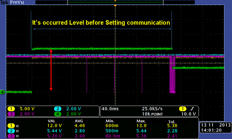
Init DAC whole of Output stage is floating to 5V output for 1ms, (blue colored line)

Is this DAC output  possible to go "0V"?

Can you control the DAC output to go "0V" ?

(notes : status was not entered the DAC Output control by I2C )

please let me know If it is possible to go to "0V" on init stage?

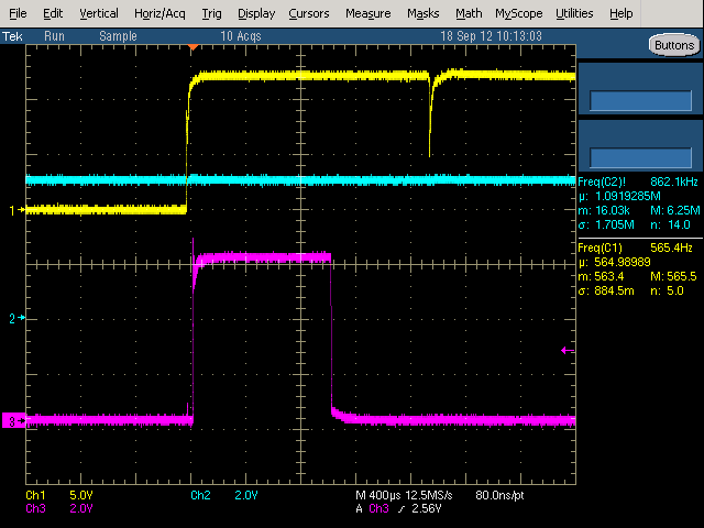
(Below waveform :

1Ch : Analog Vcc 12V,      2Ch :I2C SDA,    3Ch : DAC Output)


 Thanks,

eric.

  • Hi Eric,

    I believe I understand your question although I am not completely sure.  Are you asking if it is possible to control the power-on behavior of the BUF16821 outputs before providing the first I2C command? 

    If so, the answer can be found in the datasheet on page 10 which describes the "General-Call Reset and Power-Up" behavior of the device.  In this section it states that "When the BUF16821 powers up, it automatically performs a reset.  As part of the reset, the BUF16821 is configured for all outputs to change to the last programmed nonvolatile memory values, or 1000000000 if the nonvolatile memory values have not been programmed." 

    The following section "Nonvolatile Memory" describes the BKSEL pin.  The datasheet specifies that the signal present at the BKSEL pin will determine which of the two OTP banks are loaded into the outputs of the BUF16821 on power-up.  Therefore if you would like the BUF16821 outputs to power-up to a "0" level, then program all of the BUF and VCOM outputs to "0b0000000000", write it to the non-volatile memory, be sure you have the correct BKSEL signal, and then on power-up the outputs will start at "0". 

    Please note that the BUF outputs will not go all the way down to "0V" but rather will be limited by the given amplifier "Output Swing: Low" characteristics which are specified in the parametric table on page 3 of the product datasheet.

    Thanks and Regards,
    Collin Wells
    Precision Linear Applications

  • Dear Collin Wells,

    I've urgent problems that is burning issue after using BUF16821 for MP now :


    Abnormal Voltage after setting value of programe input,

    -> It 's set to output  value that is changed by setting value.

    Burnt Frequency rate : 0.1%, that is occurred somtimes burnt in IC or F-PCB random..

    Total MP q'ty is 10K around..

    Tomorrow I will capture the waveform both normal and Abnormal.


    Because of above issue that Gamma block was burnt on board,

    I have to change a new solution?

    Could you please recommend a new IC or a soltion in order to protect this burnng issue?

    For example,

    1) added 3-state Buffer in Gamma Buffer IC?

    or

    2) maintenance of High Impedance state IC before I2C setting program value?


    best regards,

    eric


  • Hi Eric,

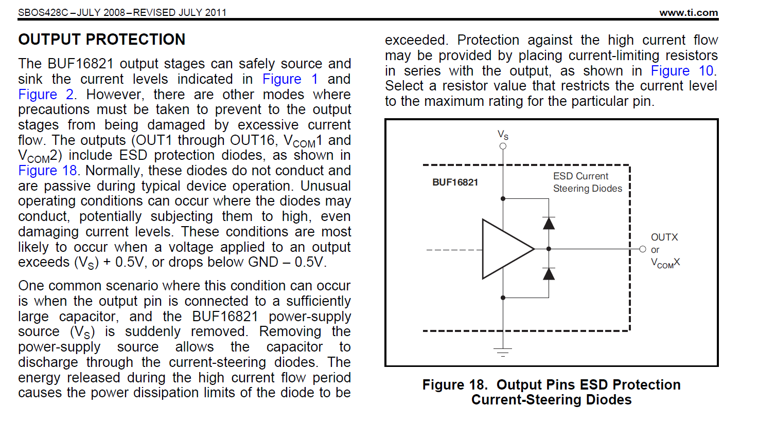
    I am now supporting the BUF16821.  The BUF16821 is a robust device...we do provide guidance to protect against damage that can occur under certain power supply conditions.  Please take a look at the section in the data sheet regarding Output Protection.  I have pasted that section here for your convenience.

  • Hi Edward Mullins,

    Thanks for your guide and I've attached a capture waveform that is offset Level.

    could you please review it?


    Thanks,

    eric.


  • Hi Eric,

    That would be the correct POR value if there is no programming to the nonvolatile memory.