This thread has been locked.

If you have a related question, please click the "Ask a related question" button in the top right corner. The newly created question will be automatically linked to this question.

Help Acquisition system with INA116

Other Parts Discussed in Thread: INA116

Hello,

I want to build an acquisition system for measuring difference of electric potential in a soil profile of 100 m, relative to a reference electrode. This system will have 50 channels and a maximum sampling rate of 1SPS. The maximum signal amplitude is 200 mV, and bandwidth is DC – 1 microHz. (Are signals of large period)

 The figure below shows a schematic of how I had thought of building this system.
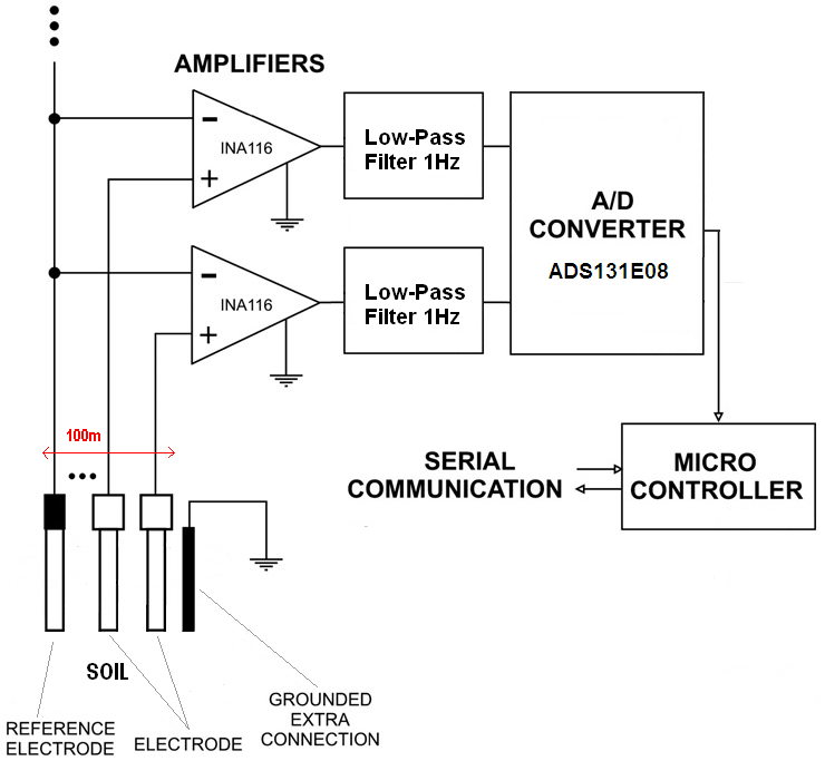
   

Upon this my idea I had several questions to ask.

 Question 1: I chose the INA116 instrumentation amplifier, because it is the amplifier that has the highest input impedance. Is it the best choice for this my case?

 Question 2: It is good idea to use a active low-pass filter of 1Hz output of INA116? Or the cutoff frequency will be more lower?

 Question 3: Can I do a active low pass filter with INA116 directly? If not, what is the best configuration?


Best regards

Ivo Bernardo

  • Hello Ivo,

    This sounds like an interesting design and I believe you have a good starting block-diagram of how you should design your system.  Please find answers to your questions below:

      1.)  The INA116 does indeed have the highest input impedance and lowest input bias current of any of our INA devices.  Therefore if your electrodes are high-impedance (typical) then you will want to use a device such as the INA116 to ensure that the input stage of the INA does not load down your sensor.  If your electrodes are lower impedance, then a standard INA may work as well.  If you do use the INA116 then be sure to use the recommended circuit board layout and properly use guard rings to protect your input from leakage current paths as discussed on page 8 of the datasheet in the "Circuit Board Layout and Assembly" and "Input Connections" sections of the datasheet.

    2.)  An active or passive low-pass filter will provide basically the same results assuming the order and type of filter are the same.  People usually employ active filters because you can achieve higher filter orders with higher "Q" than is possible with a reasonable passive R+C filtering scheme.

    3.)  It is not possible to create an active filter using the INA116.  You may apply a passive low-pass filter to the inputs or outputs of the INA but you should be careful regarding leakage current paths if you plan on taking advantage of the input impedance of the INA.

    You will also need to include a input bias current return path as described in the "Input Bias Current Return Path" section of the datasheet and in Figure 3.

    Regards,
    Collin Wells
    Precision Linear Applications