Other Parts Discussed in Thread: OPA569
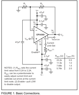
I am using the OPA569 in a design and followed the 'basic connections' diagram in the datasheet (image copied below).
V+ is 5V DC from a power brick and V- is grounded.
What is the purpose of the 47uF capacitor that bridges the V+ and V- pins? When this capacitor was in-place, we measured 1.6V drop across it when we expected the full 5V. After removing it, our circuit had no problems operating since it was receiving enough voltage to power the device.