This thread has been locked.

If you have a related question, please click the "Ask a related question" button in the top right corner. The newly created question will be automatically linked to this question.

OP07 output from 2V

Other Parts Discussed in Thread: OP07, LM358, LM318, TS321, OPA336, OPA363, OPA365, OPA364

Hi,

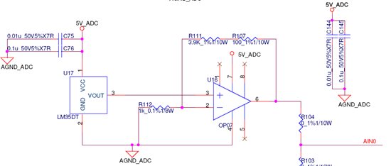
I am currently using the circuit as shown below

For this circuit I am getting an output of 2.0V at room temperature which should actually be 1.25V.

Then I removed the LM35DT and gave input to opamp through separate power supply.

When my input crossed 0.4V then my output started varying according the input.

Even at 0V input it gives output of 2V.

Earlier also I had made a isolation circuit using op07. In that case also the minimum output was 2.0V when I changed it to LM358 then it started working properly. Also there were multiple opamps in the circuit so the whole thing suited well.

I don't know the exact reason this has happened.

Currently I cant use lm358 as i have already constructed the pcb. so I placed order for samples of LM318 and TS321.

Also R103 and R104 is 0-ohm mounting option for multiple inputs and currently R103 is not connected.

Please  can you inform as to the exact reason for the same???

Will LM318 or TS321 work in this case????

Thanks Regards

Raquib Akolawala

  • The V- rail of the op-07 is tied to ground.  Look at the "Output Voltage Swing" specification for the OP07.  It can only get within a few voltage of the rails.  I'm guessing this is the problem.

    Tim

  • Hi Tim,

    For the same I had 2 idea's

    1. Firstly at 0.4V input it suppose to give a output of 2V so "maybe" input offset voltage was coming into play for the output.

    2. I also noticed nowhere in the datasheet it is mentioned that the OP07 can sink current where as the same is mentioned in TS321.

    Please let me if this reason is valid or not.

    Also will LM318 or TS321 work in this case?

    Currently I have bypassed the opamp to up my board.

    Thanks Regards

    Raquib Akolawala

  • The OP-07 has a worst case offset voltage of 130uV.  Even with a gain of 5 I don't see how that can be a factor.  I think your problem is with a combination of output voltage swing (the OP07 output is in saturation) and input common mode range (with the input at 0.4V it is too close to the rail).  For this circuit to work you need to bias your temperature sensor output into the common mode range of the amplifier and possibly provide a negative supply, depending on the range you end up with.

    Switching to an amplifier with RRIO would probably help, but keep in mind that RRIO opamps become nonlinear when they get within 50 or 100 mV of the rail.  Pay close attention to common mode input range and linear output range.

    The LM318 should have similar common mode issues and also has a much larger offset voltage that will degrade the accuracy of your measurement.

    The TS321 might work as it's input CM range included ground and the offset voltage will not contribute as large an error.  However, I cannot make sense of the output voltage swing specification so I don't know if it will work over the required temperature range.

    Good Luck!

    Tim

  • As Tim already stated, the common mode range for the OP07 is exceeded.The output range and VCC are also problems in this circuit.

    I suggest the OPA363, OPA364, OPA365, OPA,376 or OPA336.
    The OPA336 is the lowest cost and has the lowest bias current, but it is slower.


  • Dear Ron and Tim,

    Managed to get the correct LM35DT output.

    Thanks Regards

    Raquib Akolawala

    PS: Thanks for the disclaimer.