This thread has been locked.

If you have a related question, please click the "Ask a related question" button in the top right corner. The newly created question will be automatically linked to this question.

optimized photodiode for ambient light rejection

Other Parts Discussed in Thread: TLV2475

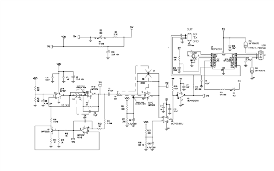
How can i optimize this circuit further more for rejecting ambient light and detects only the Green LED light ?  Thank you so much in advanced.


  • Amit,

    I am not able to read the details of your schematic. You may wish to attach a higher resolution image file. I can, however, see that the feedback to Q1 appears to be connected to the wrong node. I believe that you intend the feedback to be to the emitter of Q1.

    It is not possible to make an electronic filter for green light as there is no distinct electric signature in the photodiode response for the color or wavelength of light. You can, however, use a green optical filter to favor response to green light.

    Regards, Bruce.

  • Bruce,

    I have attached the PDF file.  Are there any inexpensive optical filter available?  I searched for the optical filter but can't seem to find one.

    Thank you

    5756.photodiode.pdf


    photodiode.pdf
  • I don't know what your standard is for "inexpensive", but Newport sells filters for optical applications.

    http://www.newport.com/optical-filters/997534/1033/content.aspx

    If you don't need a particularly narrow bandwidth, a photographic filter might work.  Try

    http://www.bhphotovideo.com/c/search?atclk=Filter+No.%2fColor_%2313+Green&ci=113&N=4077634515+4225042088

    Tim

  • Amit,

    What op amps are you using? The op amps shown in your schematic are not made by Texas Instruments.

    The schematic that you have provided has errors that will prevent proper operation. The non-inverting input of U1-B is connected to the wrong node. The collector of Q1 is connected to the wrong node. The photodiode is connected backwards.

    Regards, Bruce.

  • Bruce,

    As of now for prototype on breadboard I am using op amp from microchip.  Since i don't have TLV2475 in stock here.  I will be using TLV2475 in final design  My circuit works fine.  I am seeing the output data as they should be.  The circuit woks fine without U1-B and Q1.  As of my knowledge this two should balace the ambient light current and i can use wider range of feedback resistor in transimpedence amplifier.  I understand now the U1-B should be the half the VDD and ref.  I didn't understand the Q1 connected to wrong node and photodiode connected backwards.

    Thanks, Amit