This thread has been locked.

If you have a related question, please click the "Ask a related question" button in the top right corner. The newly created question will be automatically linked to this question.

Help with amplifier oscillation

Other Parts Discussed in Thread: INA114, INA117, INA132

HI,

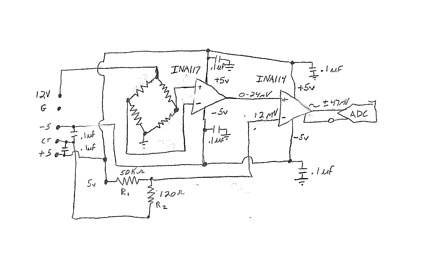
I am relatively new to opamp circuits, but I have designed one that does what I want it to do.  The problem is that I am getting a slight oscillation - more like a ripple.  There are two amplifiers in the circuit - an INA117 which feeds the non-inverting input of an INA114.  I am using a voltage divider to feed the inverting pin of the INA114 to set the point where the output goes negative or positive depending on the input.

The sensor connected to the INA117 is a strain gauge.  The purpose of the circuit is to take a unipolar mV signal and turn it into a bipolar mV signal feeding a bipolar input ADC.

The gain on the INA114 is set using a 16.9k ohm resistor to approximately 4X.  Below is my diagram.  I would really appreciate some recommendations on how to get this little ripple resolved.

  • Hello Kevin,

    Thank you for considering the INA117 and INA114 for your design.  In order to help you further, I have some questions:

    a)  Can you please attached a few oscilloscope screen captures that depict the ripple?  What is the frequency of the ripple? 

    b)  Where is the ripple observed...at the output of the INA117, INA114, or both? 

    c)  Do you observe any ripple on the inputs and/or the power supply pins? 

    d)  Is this circuit built on a PCB or 'breadboard'? 

    e)  Have you verified that the decoupling caps are placed close to the supply pins? 


  • Thanks for your response.

    a)My scope is not very good, but I know that the ripple is in the 0-20 microvolt range.  I am reading this off of a data acquisition module.  I will see if I can capture the ripple on the scope anyway.

    b)The ripple is observed on the output of the INA114 as seen by the ADC.  I'm relatively certain that the problem lies in the INA117 portion of the circuit.  The INA114 is rock solid at 2x gain.  The problem didn't start to occur until we added the INA117 and the voltage divider reference to change the output from unipolar to bipolar.

    c)I haven't observed the ripple on the power pins.  I will check that out.

    d)Right now we are using a breadboard.

    e)Since the circuit is on the breadboard, we have placed the decoupling caps as close to the pins as we could.  They are not more than half an inch apart. We could probably get them closer though.


    I'm wondering if there is a way to accomplish the unipolar to bipolar conversion with the INA114 alone.  Any thoughts?

  • Hello Kevin,

    When you add the INA117 into the design please note that the device has 25uVpp of noise referred to the output.  You may want to consider filtering the noise as discussed on page 10 of the INA117 data sheet.

    I assume you have the device soldered on a DIP adapter board. Therefore, I would solder the decoupling caps directly to the pins of the device.

    Finally, I don't see an issue with using the INA114 to convert your unipolar voltage to bipolar. You're subtracting 12mV (1/2 of the full-scale input) from the input to shift the waveform down.

  • Pete,

    Thanks for the input.  I had noticed that filter in the datasheet, but somehow became preoccupied with filtering the input.  I am going to try that to see what happens.  I would really rather only use one chip though.  Please bare with me.  I'm a newbie and I'm still brushing up my fundamentals.  So this is where I'm stuck:  my input is a 350 ohm bridge.  I am using a 12V power supply so when the bridge is balanced, I get 6V on the negative output and 6V on the positive output.  I believe what I want to do is to increase the voltage on the negative input pin of the amp to 6.012V.  The problem I have yet to solve is how to inject the additional 12 mV on the negative input.  Or am I barking up the wrong tree altogether?


  • Hello Kevin,

    No problem. Using a voltage divider to generate the 12mV signal for the inverting terminal on the INA114 is fine. However, be aware that the ratio of the two resistors is important for an accurate voltage, so you will want to use precision resistors. Also note that the resistor values can drift with temperature.

    While the overall implementation is sound, I would investigate the use of the INA117 especially if the filter does not yield acceptable results. The INA117 is very useful in very high common-mode voltage applications. You may be interested in evaluating the INA132 for this application because it has lower noise and less initial input offset voltage.