This thread has been locked.

If you have a related question, please click the "Ask a related question" button in the top right corner. The newly created question will be automatically linked to this question.

Op-amp for nanoampere currents and dual power supply

Other Parts Discussed in Thread: TPS65130

Hi there!

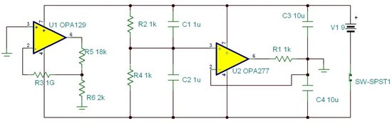
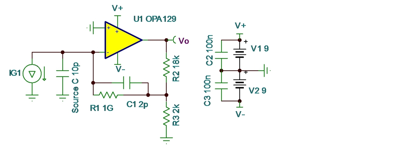
I'm physics engineering student, and next year I'll get my degree but first I must build a device for my final thesis, which is related with biophysics topic. So, it's necessary to detect currents in the nano amperes order. I think I could use an OPA129, a trasimpedance op-amp, but I would like have another suggestions (if there). Another important aspect it's relating with the power supply for the op-amp, because the final voltage reading depends on the simmetry of the dual power supply. Would be correct implement a LM7812/7912 IC (+/-12V) for this purpose? The signals to be read are in the range of few Hz to 1kHz.

Thanks for all.

  • Pablo,

    Perhaps you can provide a diagram of your measurement circuit. This would help in determining the best choice for an op amp. Be sure to show the aspect of the circuit that you believe would be very sensitive to the symmetry of the power supplies. It's not obvious why this would be the case. Also please indicate the accuracy of the measurement you would like to make and the full-scale measurement current (more specific than nanoamp range).

    Regards, Bruce.

  • Thanks for you fast reply,

    Here it's the circuit idea (based on OPA129's datasheet typical circuit). It's a simple I to V converter. Current range starts at 1 fA to 1 nA (approximately), with an accuracy of +/- 0.01 nA. The issue with the simmetry is related with experimental observations, because the best performance (voltage measurement's reproducibility) was obteined applying a battery voltage divisor like it's showed in the diagram. Although I'd like supply the circuit with a dual power supply. Sincerely, it could be an incorrect interpretation of the datasheet info, because I'm just starting in the electronics world.

    What do you think about it?

    The current input is at pin 2. All the circuit was tested into a Faraday cage (to avoid electromagnetic noise).

    Thanks again,

    Pablo.

  • Pablo,

    I don't see any real need in your circuit for accurate symmetry in the power supply voltage. I think it would simply your circuit greatly to use two 9V batteries as shown below. C2 and C3 should be located close to U1.

    Note that a 1nA input signal would overdrive the amplifier, attempting to create 10V output.

    C1 will be required for stable operation. The optimum value for C1 will depend on the capacitance of your source and stray capacitance. Depending on this capacitance, you may have difficulty getting sufficient bandwidth. It may be better to eliminate the extra gain from R2/R3. You could use a second op amp for more gain, if necessary.

    Regards, Bruce.

  • Ok, I got it. 

    So, first, is this op-amp best for my purposes? And second, if I'd like to implement a dual power supply which wouldn't be connected to batteries what IC could you recommend me (for +/- 10V)? For example, would be ok a LMXXX?

    In relation with the maximum input current at pin 2, which method could I utilize to avoid over current?

    Regards, 

    Pablo.

  • Pablo,

    The OPA129 is a good choice for this application. You could use 7812 and 7912 regulators for the power supplies. I suggested batteries to avoid the hassle and eliminate any possibility of external noise if you wanted to put them inside your shield.

    The maximum input current is related to the transimpedance gain and output voltage swing capability of the op amp. The output limitation of the op amp is approximately 2V from each supply rail (+/-10V for +/-12V supplies). With a 1G-ohm x 10, your present circuit would reach 10V output with a 1nA input current. It would have overloaded at a lower input current with your previous 9V/2 circuit.

    What is your source capacitance? You could have bandwidth limitations.

    Regards, Bruce.

  • Thanks bruce,

    I'd like consider all options for this project. In this way, I found this forum thread where somebody uses a TPS65130 (a DC/DC converter). What do you think about this possibility? Although higher frequencies could be a problem for the final voltage output reading.

    Pablo.

  • Pablo,

    My impression is that you are making a laboratory measurement. Is that correct?

    The TPS65130 would be a good choice if you were designing a production product and needed to use a single battery to power the system. In a laboratory setting, it seems an unnecessary complication that has the possibility of injecting switching noise into sensitive low-level measurements.

    Is there some reason that you do not want to use two power supplies or two batteries?

    Regards, Bruce.

  • Of course, it's a kind of laboratory measurement system. I just asked you about other possibilities because I had curiosity in the matter (having account that I'm started in the electronics basic design). Maybe this knowledge could be useful for resolve another problem.

    Thanks for all, specially your patience. I think you gave me enough bases for assume the project.

    Regards, Pablo.