This thread has been locked.

If you have a related question, please click the "Ask a related question" button in the top right corner. The newly created question will be automatically linked to this question.

Need a solution for converting bipolar output of sensor to unipolar input of ADC

Other Parts Discussed in Thread: TMS320F28335, LM4140

Dear Experts,

The inputs of a ADC ( TMS320F28335 ) is in the range of 0 to 3 Volt.

The outputs of a transducer is in the range of -5 to 5 Volt.

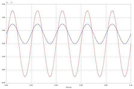
It is required to shift the output signal of the transducer to 1.5 Volt and to decrease its amplitude.

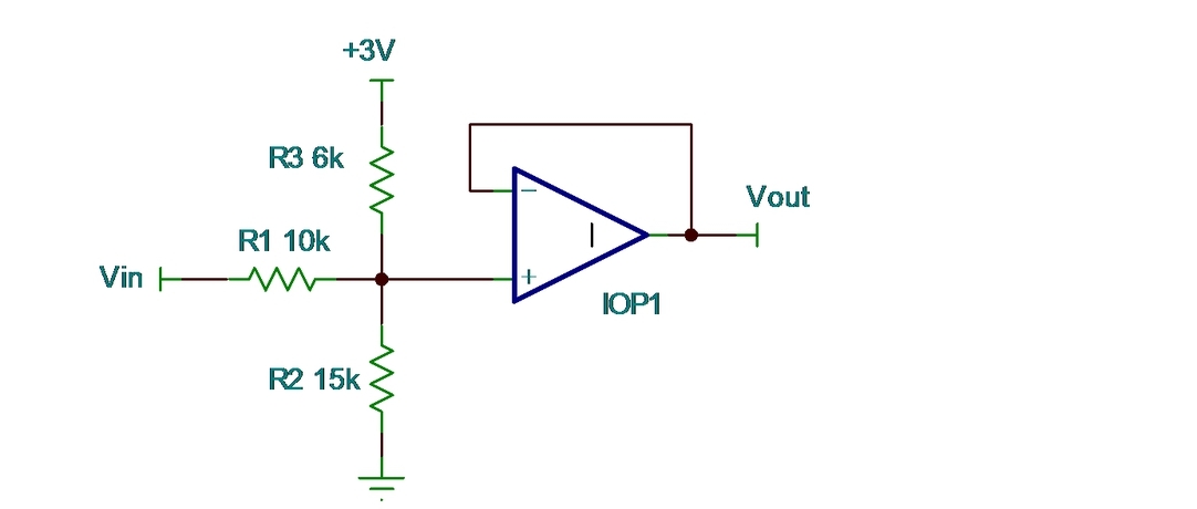
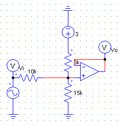
I can use the below circuit.

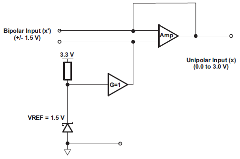
Also I saw the the below circuit in a TI application note.

May there is other solutions, I don't know!

Q1- Which solution is better?

Q2- Is there a dedicated IC for this reason?

Q3- Please suggest me a practical circuit ( contain IC number )?

Best Regards,

Ras Sharif

  • Ras,

    I think this circuit will do what you want. Do you have a 3V reference? Op amp selection will depend on speed, accuracy and power requirements.

    Regards, Bruce.

  • Dear Bruce,

    Thanks for the circuit.

    Can you compare the TI's circuit in my first post with yours?

    Regards,

    Ras

  • Ras,

    Your second circuit (with resistors added for proper operation) would be inverting. It would provide 0V output with 5V input and 3V output with -5V input.

    Your first circuit is essentially the same as my circuit. V1 is the input. V2 is the reference voltage. With R2 in my circuit, the op amp can be connected in G=1. The circuit I suggested uses the minimum number of components.

    Regards, Bruce.

  • Dear Bruce,

    Thanks for the explanation.

    I have another question; What is the difference between to use of reference voltage circuit ( reference voltage IC or Diode based ) with divided voltage? Which circuit is functionally better?

    Regards,

    Ras

  • Dear Bruce,

    I simulated your circuit.

    The waveforms are as bellow:

    The results are satisfying.

    I have the previously questioned; Does the reference voltage circuit have superiority over this circuit ( divided voltage )?

    Regards,

    Ras

  • Ras,

    I'm not entirely clear on your question regarding the voltage reference. Any circuit that accomplishes your transfer function must use a reference voltage. In my circuit, the 3V source is the reference and this must be a stable voltage to provide the accurate offset needed for the transfer function. If this voltage is changed, the resistor values must change.

    A voltage reference circuit is usually much more accurate than a zener diode. Most common zener diodes are not fully specified for accuracy and temperature drift. Furthermore, they must be biased with a specific current for reasonable accuracy. As the load current changes (as it does with signal level in this circuit) the zener current changes thus affecting the reference voltage.

    Regards, Bruce.

  • Dear Bruce,

    Excuse me. I made mistake.

    The meaning was voltage reference IC; for example LM4140 Precision Voltage Reference.


    Regards,

    Ras

  • Ras,

    Did I answer your question?  If not, then please restate it and I will try again.

    Regards, Bruce

  • Bruce,

    Thanks for your answer. I understood from it the difference between zener diode circuit and voltage reference IC.

    My previously questioned is; For providing bias voltage, your circuit is better or using of LM4140 precision voltage reference IC?

    Regards,

    Ras

  • Ras,

    The circuit I provided requires a 3V voltage reference. The LM4140 does not have a 3V output version. The circuit can be redesigned for a different reference voltage by changing the resistor values. Do you have a reference voltage available in your system? Or what reference voltage would you like to use?

    Regards, Bruce.

  • Bruce,

    LM4140 contains 1.25 V output.

    1.5 V perhaps is better than 1.25 V since the input range of ADC is 0-3 V.

    But my question is general; Which of solutions is better? to divide the supply voltage and provide a bias voltage or to use of a voltage reference IC.

    Regards,

    Ras

  • Ras,

    Sorry but I should have explained that this circuit cannot function properly without a reference voltage of approximately 2.2V or greater. The LM4140 has 2.5V and 4.096V versions. Here are the circuit values required for several common voltages:

    Vref = 2.5 3 3.3 4.096
    R1= 10000 10000 10000 10000
    R2= 30000 15000 12222 8988
    R3= 5000 6000 6600 8192

    It is better to use a quality voltage reference. The power supply may not provide sufficient accuracy and temperature stability for accurate offsetting.

    Regards, Bruce

  • Dear Bruce,

    Thanks for all the help.

    Best Regards,

    Ras Sharif