This thread has been locked.

If you have a related question, please click the "Ask a related question" button in the top right corner. The newly created question will be automatically linked to this question.

Trapezieform pulse amplifier design

Other Parts Discussed in Thread: OPA453

Hello!

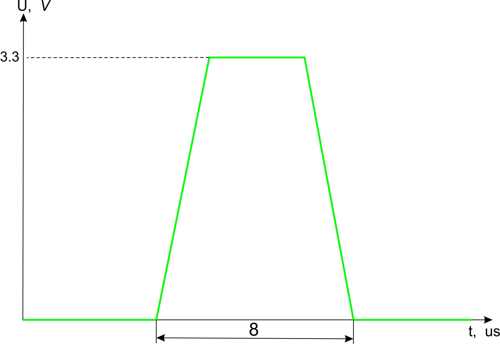
I'm developing trapezieform pulse generator. The pulse is synthesized directly by FPGA and DAC. The pulse has 3.3 V amplitude and about 8 us width (see picture).

So, I need an amplifier to increase the amplitude to 130 V with minimal pulse form distorsion.

What TI components should I use to create such amplifier?

Thanks for answer!

  • Maksim,

    It appears that the rising and falling portions of the waveform occur in approximately 2us. This would require an amplifier with a minimum slew rate of 65V/us which is faster than can be achieved with our standard high voltage amplifiers.

    Our OPA453, for example specifies a typical rising slew rate of 23V/us. It has a maximum operating voltage of 80V, In bridge mode operation (BTL) it could provide the required output voltage swing but with a maximum slew rate of approximately 40V/us. This would distort the shape of the output waveform significantly.

    So it appears that we don't have an easy solution for your requirements.

    Regards, Bruce.

  • Bruce, thank you for answer.

    Rising and falling portions are 2 us for this drawing, yes. But it is only an example. In fact, we need to provide 8 us in total and portions ratio can be different (3+2+3, 1+1+6, so on).

    So, your variant with OPA453 can be helpful for us under some conditions. Where can I see bridge mode schematics with these ICs?

    There is an circumstance, that I've forgot to mention - we need output current up to 3 A. Can the OPA453 output current be increased by transistors?

    With regards, Maksim

  • Bruce, do you mean this circuit under bridge mode connection?

  • Maksim,

    Sorry for the delay. Yes, your schematic shows a bridge output configuration. Note that this does not allow the load to be ground referenced. The load must "float" between the two amplifier outputs.

    The output current of the OPA453 obviously falls far short of your 3A goal. While it may be possible to boost the output current with external transistors, this type of circuit can be quite tricky to implement. The OPA453 is not unity-gain stable, allowing it to achieve relatively high speed. This make it much more difficult to add current-boosting output transistors inside the feedback loop.

    Regards, Bruce.

  • Bruce,

    yes, it's very desirable to us to have ground referenced load.

    So, may be there is more reasonable to use stage based on MOSFETs as shown below?

    With regards,

    Maksim

  • Maksim,

    The design and optimization of a push-pull amplifier of this type can be very tricky. If you attempt to develop such a circuit, be prepared for considerable study and effort. At the voltage, current and speed you are seeking, you will likely need an ample supply of spare parts. I also recommend keeping a fire extinguisher nearby. This is not an easy "cookbook" project.

    I see problems with the circuit you have provided. Fundamentally, I believe that any circuit with upper and lower output transistors controlled by separate op amps is likely to create trouble. It is very easy to turn both transistors on at the same time, drawing high current and creating massive power dissipation. Successful designs of this type generally use a single op amp that can supply a drive signal spanning the full output voltage range. As we discussed, we do not have an op amp with sufficient voltage range to do this which is the reason for bridge operation.

    Regards, Bruce.

  • Bruce,

    I agree with you, this high-voltage and high-current design is not easy. I have an experience with switching power supply, so fire extinguisher is always nearby))

    I've understood you about minuses of two opamps as preamplifiers. If you have any schematics applicable for my case, would you please provide me with them? I'm have more experience with MCU and FPGA than analog devices, so I'll be thankful for any information.

    With regards,

    Maksim


  • Maksim,

    I cannot recommend any specific circuits. Anything I could imagine would require considerable engineering and refinement.

    The amplifier you need resembles an audio power amplifier. You can find many circuits for "homebuilt" audio power amplifiers on the internet. Most would achieve the current level you are seeking but would not have voltage capability. These circuits could serve as a starting point for a design. Most would not have the slew rate that you want.

  • Thank you, Bruce!

    I'll try to work in this direction.

    With regards,

    Maksim