This thread has been locked.

If you have a related question, please click the "Ask a related question" button in the top right corner. The newly created question will be automatically linked to this question.

Need help sensing 4 amps on 120VAC line

Other Parts Discussed in Thread: OPA330, OPA2330

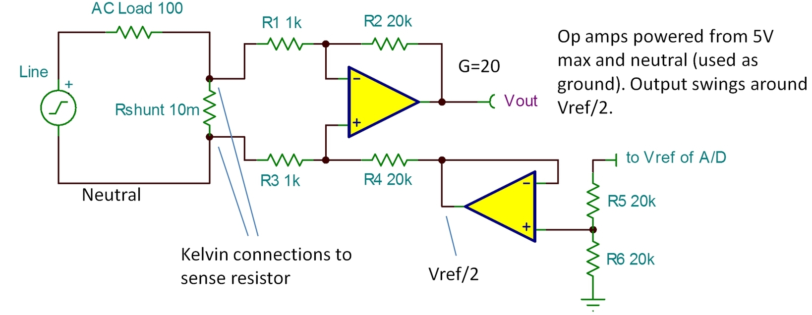
I am looking for a way to sense when the current draw in a product rises above 4 amps (no-load is about 2.5A).  I'm thinking a difference or instrumentation amplifier is the way to achieve this, but I've never designed with one.  My plan is to use a 0.01-ohm resistor in either the Line or Neutral conductor to detect the rise in current, feed the voltage across the resistor (40mV) to the amp, then send the output to the ADC of a microcontroller.    Since this will be plugged into a US outlet, the sustained current limit would be 15 amps.

Any suggestions as to which TI part is optimal for this?

  • Eric,

    Virtually all commercial products require galvanic isolation from the AC line. Most devices achieve this with a transformer, either at line frequency or with a higher frequency switching circuitry that is run off the AC line. The high frequency is then transformer coupled. Everything on the input side of the transformer (whatever type) is insulated from contact by the user.

    So unless you are making a device that is fully insulated (nothing, including ground, can be touched by a user), you need galvanic isolation of the current measurement signal. Can you provide a bit more detail on the type of device you are making?

    Regards, Bruce.

  • Bruce,

    Thanks for the reply.  This circuit will be going into a power tool, which is double insulated.  So the user will not be able to touch these components.  The current will be the same on Line or Neutral, so I'm open to either high-side or low-side sensing options.  There seem to be more parts available for low-side (lower common mode voltage), so that might be the best path.

  • Eric,

    Okay... excellent. No need for galvanic isolation in this case.

    Low-side is easier if you have the option as you remove the need for high common-mode rejection. The decision of how to sense might well be determined by exactly what you want to do with this signal. Possibilities might include one of our simple instrumentation amplifiers or possibly a four-resistor + op amp difference amp. What comes after the measurement? What will you do with the signal?

    Regards, Bruce

  • I'm going to send the output of the amp to the ADC of a micro. If the sense voltage exceeds 40mV, I'm going to flash an LED.  That's the extent of this prototype right now.

  • Sorry, Eric. I didn't read far enough in your first post. I was too concerned about killing someone without galvanic isolation.

    I think the best solution might be a simple difference amp. Four 1% resistors around an OPA330 op amp. This link gives some background...

    Making Your Own Difference Amp—sometimes 1% resistors are good enough

    The resistors could be 1k and 20k for a gain of 20, or so. The gain configuration also helps with CMRR. The "ref" terminal (R4) would need to be offset with a low impedance voltage, mid-scale of your a/d converter input. The output of the amplifier would swing +/- around this pedestal voltage.

    Regards, Bruce.

  • Thanks a lot, Bruce. I must admit I'm lost on the technical details. Where do the 1K resistors go? The article you linked showed 4 resistors of equal value. 

    Also, would the output of the amp be referenced to the AC neutral?  If so, I'll need to change my plan of powering the amp and micro from a 9V battery + voltage regulator (for prototyping purposes).

  • Eric,

    This would need refinement but here are the basics...

    Regards, Bruce.

  • Bruce,

    In your diagram, are both op-amps the OPA330, or is the second one a standard (not precision) amp?

    And just to clarify, I won't be able to power the amps from the 9V + regulator option, correct?

    -Eric

  • Eric,

    You could use the dual version, OPA2330, or a lower precision op amp for the reference buffer. The input op amp may not need to be so precise, either. Depends on how you process the waveform when you digitize. You might, for example, take out all offset by averaging the waveform.

    You can't power these op amps from 9V. You could use a 5V LDO off of a 9V battery to run the op amps during experimentation. Low side of the battery, LDO and op amps connect to neutral.

    Regards, Bruce.

  • Bruce,

    Right, I'll be using the 9V battery with a regulator to get the 5V.  I just wasn't sure if I could connect the low side of the battery to neutral or not.

    Thanks for all your help!

    -Eric