Because of the holidays, TI E2E™ design support forum responses will be delayed from Dec. 25 through Jan. 2. Thank you for your patience.

This thread has been locked.

If you have a related question, please click the "Ask a related question" button in the top right corner. The newly created question will be automatically linked to this question.

XTR117 issues (Vreg don`t have 5v)

Other Parts Discussed in Thread: XTR101, XTR117

Hi there, i'm using a XTR117 to study the voltage-to-current method for 4-20mA output signal, this is the only ic available for me at this moment (ordered a xtr101, seems to be more flexible, i`m right?).

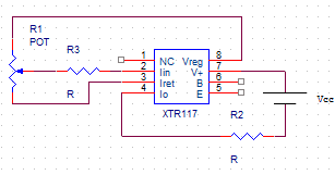
i print a pcb to solder the xtr and i've tested it following the diagram on pg1 of datasheet using a potentiometer as sensor:

Where:
R1 = 10k Ohm
R3 = 8k Ohm
R2 = 250 Ohm
Vcc = 9 v 

i'm using a multimeter to measure the voltage on the R2 (the load) and the variation on the voltage it's 10mV maximum...if i plug the multimeter to measure current in serial with the load got 20mA of measuring and no variation.

after burn my brain and make a lot of testings, including using a dataTaker DT82E (amazing machine!) to measure current loop ...nothing happens..

so.. i unplug my "sensor" and just feed the xtr with vcc, if i measure Vreg with Iret, i've got only 3.59v! must be 5v, right?

i'm totally lost, can anyone help me?

  • ok...i didn't realized that my vcc was too low for supply all the diagram (xtr needs 7.5v + 5v for reading at R2 is the minimum required..) now Vreg can supply 5v using ~16v of vcc) just need some tweaks of the R's values for proper variation i guess..

  • See attached for some more info on 4-20mA transmitters and also a TINA SPICE equivalent of XTR117 you can use to try in TINA SPICE simulator avaialbel at:

    http://www.ti.com/tool/tina-ti

    4-20mA 2_3 Wire.ppt
  • XTR117 TINA SPICE Circuit attached.

    XTR117 Circuit.TSC
  • Thank you Tim, the tspice circuit it's really helpful!

    I guess something is very wrong on my way of testing it... because on tspice the xtr117 works flawless but in breadboard not.

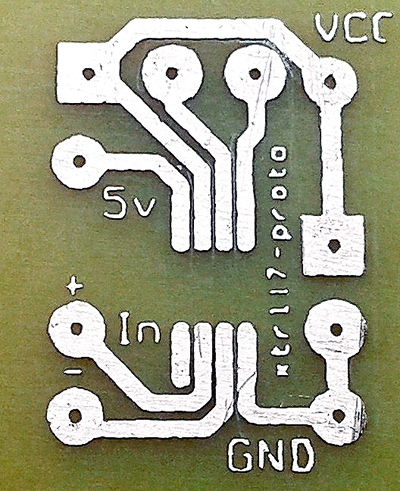
    please Tim, can you take a look on my board design to connect the xtr on any standard breadboard to see if i have done something wrong?! i can't understand what happens =(

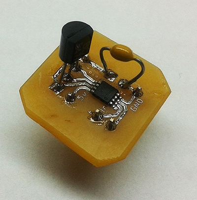
    it's a BC547A (NPN transistor) and a 100nF capacitor (i don't have a 10nF available here)

    if anyone wanna make a board, contact me! i will send the .dxf, .prn and .max files from Orcad Layout 9.2.3!

    if i plug a 1.5 volts battery between Iin and Iret with a 30k resistor between + and Iin, the Iout would be 5mA, but the Iout floats between ~28-36mA...start at ~36mA and will going down slowly until stop at ~28mA... 

  • Make sure the IC is in the correct way so Pin 1 (NC) in the right place on your PCB.  Refer to attached and confirm your test setup is as I show including V1 set to 9V.  If your setup is differnet than this it can be causing a problem. Also confirm correct transistor connections per attached.  Let me know if this fixes it. 

    Saulo XTR117.pdf
  • yes Tim, it's exactly that way!

    i've figured out the problem, it's some capacitance issue on the transistor! the way of the current drop seems to have the same behavior of a capacitor. Then i removed the transistor (because, for testing it's needless) and the current drops to ~24-->21mA... so i raised up my capacitor and works flawless now. :)

    i'm not using a smd transistor and the traces are very short.. maybe this is causing some parasitic capacitance...

    Next step: piezoeletric sensor integration to the circuit and a dc-dc power supply for stability and protection (seems to be better limit the voltage before the xtr to remove the transistor away) :)

    Thank you Tim, i really appreciate your help!