This thread has been locked.

If you have a related question, please click the "Ask a related question" button in the top right corner. The newly created question will be automatically linked to this question.

XTR117 failing....

Other Parts Discussed in Thread: XTR117, INA122

Hi, we have implemented a strain gauge to 4-20mA converter using the XTR117 and are seeing more failures in the field than we are happy with.

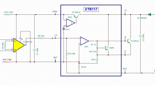
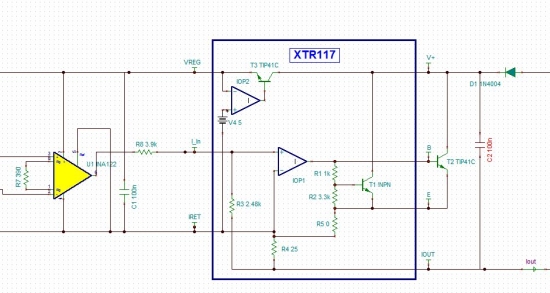
The circuit uses an INA122 instrument amp to amplify the strain gauge signal and the rest of the circuit is as per figure 1 of the  datasheet (external transistor, and a series diode for reverse polarity protection). series resistors limit the sensor bridge current to about 1.3mA 

The observed symptom is 0V from VREG. With the rest of the IC functioning normally. 

In our bench testing, we observe that the VREG output is quite robust and tolerates short circuits.. Actually, in our bench testing, we are unable to get the devices to fail at all..

Could a voltage transient on the supply cause this fault?

Thanks

PK

  • Hello PK,

    Just to double check things, do you mind sharing your schematic?  If you don't want to post it to the forum let me know your direct e-mail and I'll contact you so you can send it to me. 

    Although the XTR117 is pretty robust on it's own to industrial transients it's usually recommended to include a transient protection device that will limit the loop-supply to less than the +50V absolute maximum voltage for the XTR117.  Violating the absolute max ratings can do all sorts of strange things including possibly damaging VREG. 

    Otherwise, are there any external connections to VREG or any way that the output current or voltage on the VREG pin itself could be experiencing a transient?

  • Re robustness, I agree, we've found no real problems (before now)

    I've been modelling it in Tina today, all seems good. The clip here is what is actually on the board.. The Instrument amp front end is identical to one we use on several other products, the rest of the circuit is pretty vanilla... VReg is used to excite the sensor bridge but current is limited by the 1.58K resistors..

    We're off to the EMC lab tomorrow to do some susceptability testing.

    PK


  • Hi PK,

    I agree, the circuit looks pretty straight forward and I don't see any issues.  

    I'm interested to see what you find during EMC testing.  Although some customers experience some performance related issues (offset voltage, gain error) in the presence of strong EMC fields, I haven't dealt with any hard failures like the one you're describing.  During testing, will you be applying radiated or conducted emissions?  If radiated, do you have the PCB in some type of final potted enclosure?  If conducted, will you only be applying the conducted EMC to the V+ pin, or others? 

    Are you intending to run any other IEC tests such as electrically-fast-transient (EFT), electrostatic discharge (ESD), or Surge?

    Finally, is there any way that the final customer will have access to accidentally "zap" VREG directly, or are the only electrical connections on your final module the V+ and IOUT signals? 


  • OK, a grand worth of time in the EMC lab later.....

    We stuck with conduced fast transient testing as we figured this would give us the quickest results. Our circuit implements a two wire 4-20mA driver. So there's no real earth or ground point to clamp to.

    What we found was that the spikes, induced in the 4-20mA loop were coupled into the leads of the strain gauge load cell (because there's no ground to filter/clamp them too).

    The units were failing at 2KV bursts (industrial requirement is for 4KV)

    If the shield on the load cell cable was earthed then the capacitive coupling between the load cell connections and the shield resulted in high currents flowing which killed the XTR117. Just clamping the voltage across the input and return terminals to 50ish volts improved ( ie we could take 2.7kV bursts) the situation, but didn't get us there.

    What got us to 5KV was adding clip on ferrites to the load cell lead.. In practice, this means we have to add ferrite beads or inductors to the outputs of our board... We'll probably add an earth connection and some clamps too. But I just know that no-one is going to use it......

    PK