This thread has been locked.

If you have a related question, please click the "Ask a related question" button in the top right corner. The newly created question will be automatically linked to this question.

ina333 -- instrumentation amplifier problems

Other Parts Discussed in Thread: INA333

I am using an INA333. I currently have no gain resistor (Av = 1) and running a 200mVp-p 150Hz sine wave into it. I am running single supply with 3.6V. I am finding that I must supply a Vcm on the input > 1.4V independent of Vref. For example if I set Vref = 1.6V and reduce Vcm below the ~1.4V threshold I get periodic partial cycles of sine waves with dead time between these cycles. The dead time is = Vref. This is occurring on a demo board with the part as well. I suspect it has to do with instrumentation amps and I don't understand them could you please explain? Ultimately my design will work with sensors like thermocouples where I will have no knowledge of the Vcm on the input (other than it is positive and below Vcc). In this instance I would like to configure the board where Vref = 0, the amp disregards the Vcm and measures the thermocouple voltage and I get full range for the A/D (ground to VCC).

  • Steve,

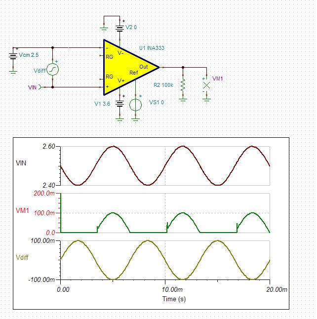
    With 200mVpp input signal and Vs=3.6V, INA333 in G=1 should work fine for 0.1V<Vcm<3.5V - see simulation results below.  Thus, I believe there must be something wrong with your configuration.

    Make sure to provide the input bias current path to the inputs of the INA333 using Vcm supply voltage - for this reason, you may never float Vdiff and must control the Vcm in such a way that the internal nodes are NOT collapsed against one of its rails- in case of Vdiff=200mVpp, this requires Vcm to be between 0.1V to 3.5V (Vdiff/2 away from either rail).

    Please use the attached circuit to simulate your conditions and if you continue having problems, please make the appropriate changes to the schematic and send it back to us.

    INA333 steve.TSC
  • Marek.

    Can Vreference be less than Vcm?  I have Vref = 0 and Vcm=2.5V.


    thx

    Steve

  • Steve,

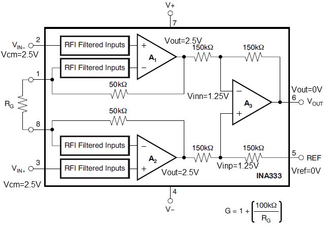
    I thought you used Vref of 1.6V and not zero.  Vref may be lower than Vcm but NOT zero if you want to apply a negative input signal - see INA333 internal voltages:

    For Vcm=2.5V and Vref=0V, the Vout=0V (see above) and ANY negative signal (where Vin+ < Vcm) will NOT result in a change in Vout since the output would have to go below its negative rail (see below) - this is never possible without an external pull-down resistor.

    This would result in the clipping of the output at Vout=0V for the lower half of sinusoidal input signal - see below. The output glitch coming out of the negative rail seen below is caused by the recovery of the output from a saturated (overdriven) condition.

  • Marek.

    Sorry for the confusion.  In my design I have a Vref = 1/2 Vcc, buffered through a voltage follower.  I have a resistor population option on the Vref of the INA333 that allows me to ground this pin or let the output of the voltage follower supply 1/2Vcc.  In the  instance of a thermocouple I wanted to populate R such that Vref was grounded and in the instance of a strain guage I want to populate R with 1/2Vcc.  See attached schem.  R7, R10, R11 and R14 allow me to supply 1/2Vcc as Vref and or Vcm to inputs.  In the case of the strain guage R10 and R14 are populated.  Sensor Connector: Pin4 measures 160mV, Pin3 measures 150mV, Pin2 measures 0V and Pin1 measures 10mV.  I currently have no gain resistor.  My A/D1 pin measures 0V.  Why is this?  I run a thermocouple into the same design with Rg= 470 ohms and it seems to work fine.  According to data schem I have a Vdiff of 150mV - 10mV = 140mV with a gain of 1.


    3108.Schematic Prints.pdf


    thx

    Steve