I’m sending you some details about the circuit and the problems: see Fig1
The problem is that the output of the PGA280 has chopping noise on the output. By my measurement it is a 1.2 MHz, 700uV RMS noise, taken with a multimeter. With 100 KSPS sampling on the LTC2376-18 there is about 24 LSB peak-to-peak noise on our measurement, which is this chopping noise aliased to the measurement. Does TI have some better characterization of this noise, so we can estimate the required output filter? The only information I was able to gather about the noise, is coming from the datasheet, it mentions: “An external, passive, low-pass filter after the output stage is recommended to remove this switching noise”
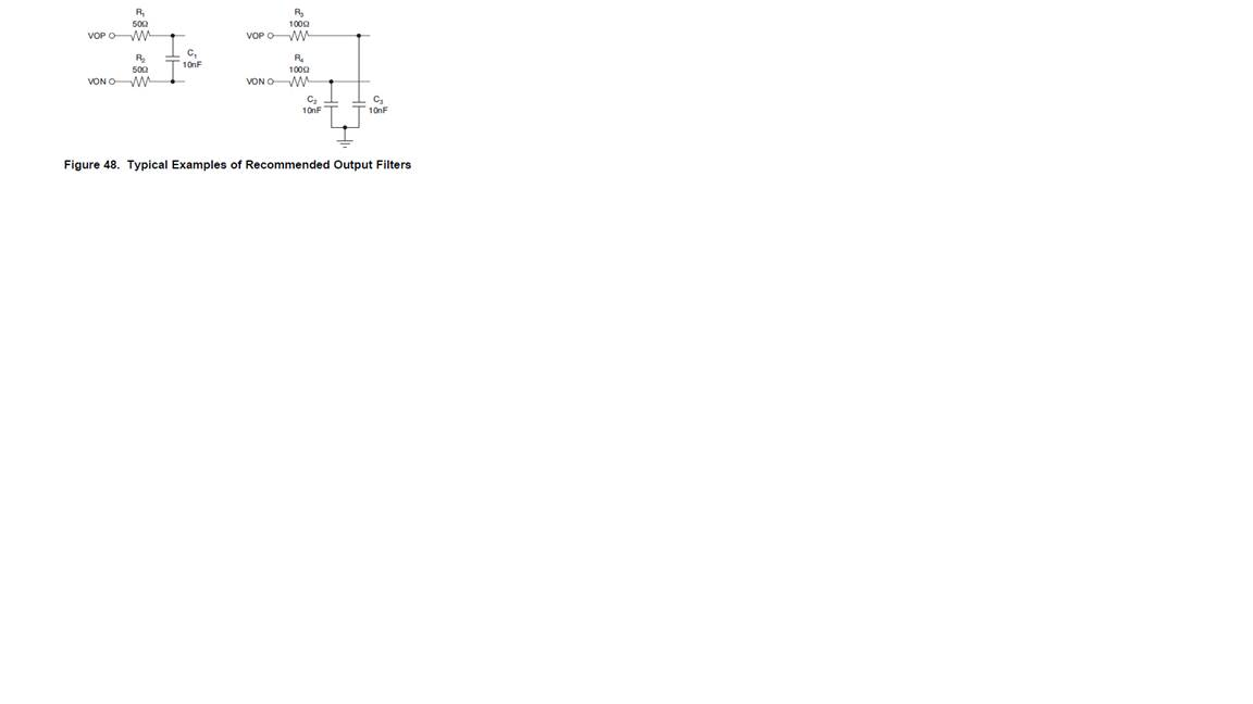
see Fig2
These circuits were tried, with almost the same result. Increasing the value of the resistors/capacitors lead to false measurements on the ADC, as the PGA280 wasn’t able to charge the sampling capacitor fully.
We are measuring multiple signals with PGA280, it has a strict timing involved. The circuit must have a settling time of ~36uS after the PGA280, and the 18 bit noise resolution is required.
We are considering implementing an additional stage between the PGA280s and the LTC2376. To avoid an additional prototype cycle, we need more information on the noise of the PGA280.
Also, if TI has some recommendation for the filter, which keeps the DC accuracy of the circuit, while drives the ADC sufficient, we will consider using it.