This thread has been locked.

If you have a related question, please click the "Ask a related question" button in the top right corner. The newly created question will be automatically linked to this question.

OPA847 PSpice Simulation

Other Parts Discussed in Thread: OPA847, OPA843, OPA846

Hello everybody,

I have downloaded the PSpice Model of OPA847 from the TI Homepage.

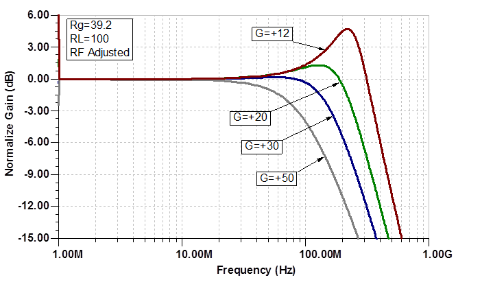
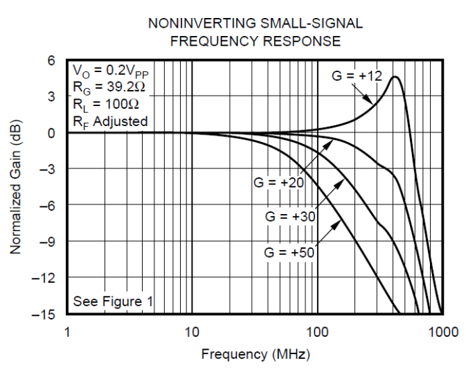
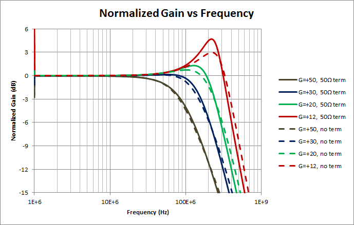
For the beginning I want to simulate small signal with the simple circuit shown on the Fig, 1 Page 10 in the datasheet. After this simulation I should get the frequency response curves for the noninverting small signal on the Page 4. For instance for the G=+12 the -3dB Bandwidth schould be arround 600 MHz. This value is also appeaars in the electrical characteristics. In fact if I simulate the circuit shown in Fig. 1 I get ca. 420 MHz instead of 600 MHz for G=+12. What is wrong?

Could every body help me.

Many Thanks

Juri


  • Juri,

    One thing to keep in mind. SPICE is a great tool that can help you check proof of concept designs and to evaluate basic performance to get an idea of how a device would operate in your configuration. However, because it uses simplified models and ideal components that do not capture every characteristic or non-ideal effects, it makes it impractical to evaluate exact performance. The best approach is to design your circuit in SPICE, simulate and give yourself some margin, then build it on a PCB and evaluate on a bench.

    That being said, the OPA847 is a decompensated amplifier that operates the best at gains above 20V/V. It can be used below that, but as you can see the gain starts to get quite a bit of peaking around +12V/V. Note that about 6dB of peaking is a sign of instability. For a good stable design, you generally want a flat response (some peaking is ok, ~3dB or so), and you want to be operating in the flatband.

    Even though this is stable and you get more bandwidth, you really wouldn’t want to design your circuit to operate that close to the cutoff frequency or rely on the peaking for "enhanced gain".

    I ran the simulation with the conditions shown in the datasheet and found that the curves were actually very close at high gains. It is just the lower gain responses that are off. This is expected though, because a SPICE model is generally optimized for stable conditions for general purpose use. This allows for the greatest number of use cases and still demonstrates the basic capabilities of the part.

     Also keep in mind that this is on a log scale, so small changes in response can actually turn out to be over 100MHz difference in bandwidth.


    If you are looking for a more stable amplifier at a gain of +12, I would suggest the OPA846 or OPA843 from the same family of devices.

    Regards,
    Luke Lapointe
    High Speed Amplifiers

  • Luke,

    Many thanks fpr the answer. Your simulation looks very close to the datasheet.
    Unfortunately I can't attached my simulation files (something wrong with the insert function). If it possible, could you give me your email adress then I will send you a pdf. with the circuit and simulation results. For the simulation I have used the circuit from the Fig.1 but without 50 Ohm resistance on the output. The Rf is adjusted:
    G=12; Rf=117 Ohm
    G=20; Rf=353 Ohm
    G=30; Rf=1.2 k
    G=50; Rf=12.3k

    but I can't get the suitable curves.

    Best regards


  • Juri,

    One quick thing I notice is you are computing gain in dB and the datasheet is referring to gain in V/V.

    The values I used to get my plots were:

    G=12; Rf=430 Ohm
    G=20; Rf=750 Ohm
    G=30; Rf=1.1 k
    G=50; Rf=2k

    Try these out and let me know if that helps.

    Regards,
    Luke Lapointe
    High Speed Amplifiers

  • Luke,

    With your values of Rf  I have get ca. 400MHz bandwidth instead of 600 MHz in datasheet.
    With the inverting circuit the bandwidth is much smaller ca. 200 MHz.
    I Would like to show you my simulation results. How can I do that? Can I send you the email? I am new in the community. Is your email adress on the homepage?

    Juri

  • Juri,

    I send you a message with my e-mail included.

    Also, in my simulations the bandwidth shows about 400MHz or so for a gain of +12V/V as well. This is to be expected as discussed previously.

    The other thing to point out. You said you simulated without the 50Ω input termination, but this actually changes the response (see below). 

    It is more accurate (and true to how it will be used in the system) to include it. I simulated with the config below.

    Let me know if this helps.

    I will also be available through e-mail.

    Regards,
    Luke Lapointe
    High Speed Amplifiers