This thread has been locked.

If you have a related question, please click the "Ask a related question" button in the top right corner. The newly created question will be automatically linked to this question.

INA 333 working

Other Parts Discussed in Thread: INA333, TINA-TI

I have a INA333 circuit which I am using for first stage amplification.

Present configuration which I ran in TINA-TI is attached with this query as a jpeg file.

 INf

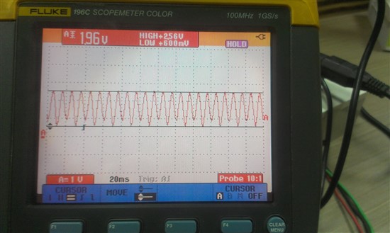
The simulation runs fine but the realized schematic doesnt give a perfectly stable output.I am providing the input (20mV p-p)from a function generator and the gain for below output is 100.

Regards

Dilbagh Singh

  • Dilbagh,

    Unless the output of your function generator is floating (as opposed to ground referenced) you may not be able to add a common-mode voltage to your input signal in the manner that shown by your TINA simulation. Also, using a simple resistor divider for your reference voltage will contribute error in the INA333 because the resistor divider degrades the accuracy of the internal matched resistors. Try adding an op amp configured as a buffer (gain = +1) between the resistor divider and the reference pin of the INA333. 

  • Hi John,

    Appreciate the prompt reply.

    "Unless the output of your function generator is floating (as opposed to ground referenced) you may not be able to add a common-mode voltage to your input signal in the manner that shown by your TINA simulation".Could you re-phrase this sentence ?Perhaps elaborate a bit.

    And yes am aware of the instability that can be caused by a voltage divider circuit.I will implement a buffer this time around.

  • Hi John,

    A small update :

    I have implemented the buffer in my circuit.Unfortunately, the problem persists.

    Regards

    Dilbagh

  • Dilbagh,

    Many function generators have their outputs referenced to ground (the outer conductor on the BNC connector) which makes it difficult to add a DC common-mode voltage to them, this was what my previous comment was referring to. Have you measured the value of the actual gain resistor that you are using? A 1010.1 ohm resistor is necessary for the gain of the circuit to be exactly 100. Also, is there a load resistor on the output? If the INA333 is trying to deliver excessive output current, its output voltage swing will be limited. Finally, does the circuit behave in a similar manner at all frequencies? If you increase the input frequency to 200Hz, what does the output look like? 

  • Hi John,


    "Many function generators have their outputs referenced to ground (the outer conductor on the BNC connector) which makes it difficult to add a DC common-mode voltage to them"

    This is true for our function generator i.e.it is referenced to ground.

    Have you measured the value of the actual gain resistor that you are using?

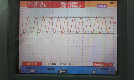
    Currently am operating for a gain of 1000V/V for which I have a gain resistor of 100Ohm (~1001 gain).As of now the output is significantly better than the first image I sent you.

    Also, is there a load resistor on the output?

    Initially there was no load resistor at the output.Later,I connected a 10k pull down at output but the response was more or less same.

    Finally, does the circuit behave in a similar manner at all frequencies?

    I noticed that the output voltage goes down as I increase the frequency starting from 100Hz.

    The datasheet mentions -3dB Bandwidth of 350Hz at a gain of 1000.Experimentally it settles at around 340Hz.


    Configuration for the below output: Input: 2mV(p-p) Gain:1001 Frequency:100Hz

    Regards

    Dilbagh Singh