A related question is a question created from another question. When the related question is created, it will be automatically linked to the original question.
If you have a related question, please click the "Ask a related question" button in the top right corner. The newly created question will be automatically linked to this question.
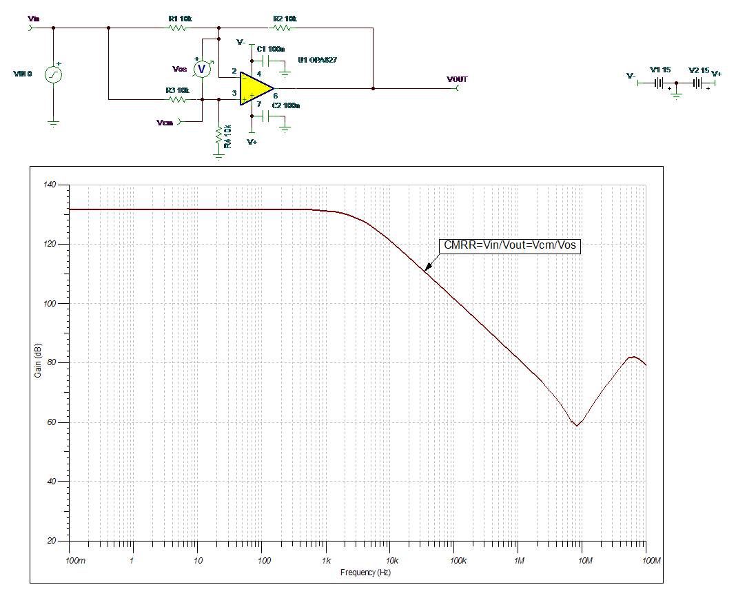
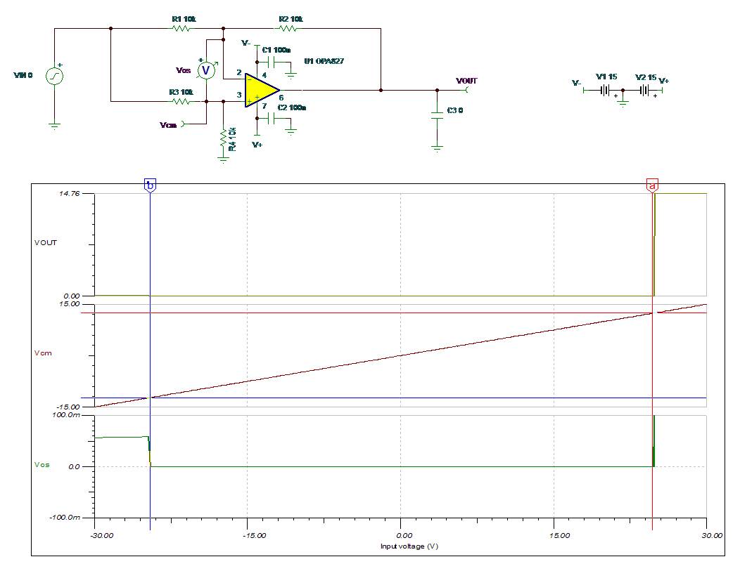
What amplifiers are you comparing? Below please see the circuit configuration (difference amplifier) used for testing ac CMRR and common-mode input range.
I have also attached Tina-TI schematic for you convenience.
Is this circuit actually used to test op-amps and provide the CMRR graphs in their respective datasheets? I have always used a similar circuit, but I include a buffer on the output inside the feedback loop to null out the output impedance of the amplifier I am simulating.
Also, if CMRR = Vcm/Vos, does this not also include the gain error and not just the CMRR of the amplifier itself?
For ac CMRR graph (using a difference amplifier configuration as shown above), CMRR=Vcm/Vos=Vin/Vout BUT for dc CMRR=(delta_Vcm)/(delta_Vos).
Using a follower configuration (G=1) to measure CMRR would result in CMRR and comparable AOL (gain) error since AOL=(delta_Vout)/(delta_Vos). That is the reason for using instead a difference amplifier configuration for measuring CMRR where Vout does NOT move (to the first-order) with Vcm so there is effectively no gain error (Vout=2*Vos).
If you want to be splitting hairs, however, and assume AOL=120dB and CMRR=120dB (1E6), as you move the Vcm by 10V (using a difference amplifier configuration) Vos changes by ~10uV (10V/1E6) - this in turn would result in Vout change of ~20uV (Vout=2*Vos) which in turn would cause a gain-related Vos error of ~20pV (Vout/AOL=20uV/1E6); but 20pV gain error would result in CMRR: 20*log[10V/(10uV+20pV)]=119.999983dB - the error is well below the noise level of any amplifier.
Also, since an output impedance of the amplifier influences the actual shape of the CMRR curve over frequency, no output buffer should be used to generate CMRR graphs.
Thank you for the detailed explanation. I have pulled a few papers in the past and one IEEE paper proposed 5 different circuits to measure AC CMRR, and the final proposal was the buffer inside the feedback loop to eliminate the output impedance. The argument was that would be the "true CMRR" of the amplifier, but in the real world I can certainly see how and why the output impedance comes into play.
Yes, of course, the resistor matching of difference amplifier gain MUST be above of dc CMRR you try to measure. Therefore, if the goal is to screen the OPA827 for dc CMRR of e.g. 114dB or better, you must use resistors with matched ratio of at least 0.0001% (120dB) - in doing so, you will measure a true CMRR and not just a resistor matching ratio.
The tightest tolerance I have been able to find is 0.005% and those tend to be very expensive. Would it not be easier to measure with a lower tolerance, say 0.01% to achieve the slope of the CMRR, then extrapolate back to the DC value?
The matching of the resistor ratios effects only dc CMRR and it should have no effect on the CMRR slope - thus you may determine the slope and extrapolate it to dc value (minimum dc value?); of course, 0.01% matching of the resistors will allow you to measure dc CMRR of ONLY 80dB or less and the question is whether you can live with the minimum specified CMRR parts of 114dB (110dB over temperature) since your screen will not give you ANY information about the true dc CMRR value of each unit. Also, if you do not need to screen the parts for dc CMRR, why to do it at all? The CMRR slope is a function of the process and circuit topology and thus effectively should be identical for all units.