This thread has been locked.

If you have a related question, please click the "Ask a related question" button in the top right corner. The newly created question will be automatically linked to this question.

coil amplifier

Other Parts Discussed in Thread: TLV2465, LMP91050, LM7705

Hi

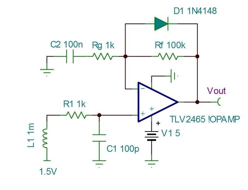
I am trying to amplify very small currents/voltages from a coil I have (the coil is a sensor - current 4uA voltage 0.2mV). I am I used ina 2332 but it doesnt do the work so I changed it to tlv2465. The problem is that the offset in this amplifier is so big that my signal is unnoticeable.

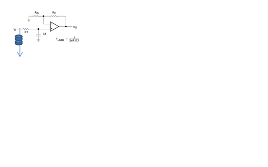
maybe I am not connecting it in the right way but I connected it exactly as shown in figure 51 in the data sheet (1 of the coil leg connected to V1 and the other ground) and it didnt work (rf=100k fg=1k).

what I want to do is to connect the coil between the 2 amp legs (+ and - ) give it small off set and get the result amplified.

do you have an example circuit how to do it? is it possible to do what I want with the amp? do you have better amp for this target (it have to be supper low power) 

Regards,

  • Hi

    not sure about your total set up, but if you have a µC in your system and your coil can be moved to a common mode offset, have a look to the LMP91050. The advantage of this part is, it is a two stage amplifier, with pretty low input bias. Most important, it has an integrated offset DAC, which allows you to actively compensate for any offsets in your system.

    Andreas

  • hi

    thanks for your answer, unfortunately the amp you offered is too big and consume too much current for our application.

    because my question was not clear I added a drawing.

    this is what I did. whene I connect pulse generator it is working with off set but when I connect a coil (or wire) const off set (instead of 0) in the output why? I wanted to get a reference drawing to how I should have done it because I have very big offset.

    H i


    .


  • or sam,

    Your diagram is not so clear. It appears that you may be connecting the coil with one connection to the amplifier input and the other to ground. What is the power supply voltage on your amplifier. This circuit will require a positive and negative power supply voltage to operate properly.

    Regards, Bruce.

  • Hi

    I do not need negative output.

    first of all I want this to work only for positive voltage in the coil (negative will result output 0).  after this will work I will connect an offset voltage -1mV to the + and this will be my off set and in that way I will be able to see the so called negative voltage from the coil.

    is it make sense to you?

    The problem is that I cant make it work because the offset voltage if the amp is to big and I cant zero .

    how can I lower this offset (when I connect wire between the + and - I see offset and not 0...)

    thanks in advanced,


  • Without a negative supply voltage, offset voltage and output voltage swing limitations will cause a "dead band" near zero. It will requires some substantial positive input voltage to cause a positive-going output voltage. An alternative is to provide a small positive bias voltage on the low side of your coil--perhaps about 0.1V. If you you need further assistance, please provide a readable schematic showing resistor values and power supply voltage.

    Regards, Bruce

  • Hi

    yes, what you reffer as- bias voltage is what I ment when writing that I want to add offset of 0.1mv. bias of 0.1v amplify by 100 will result 10v in the out put which is more than my supply. I will draw the circuit tomorrow in orcad and will send good drawing so you would see but my problem is that even when connecting both amp legs (+ and - ) I see offset.

    Regards,


  • Hi,

    think now I am getting closer to understand your problem. You can add a LM7705. This is a small charge pump, generating about -230mV. If you connect this to the negative supply of your amplifier, GND is far enough away from its negative supply and ev erything should work fine.

    Andreas

  • or sam,

    Here is a possible approach for your circuit:

    C2 reduces the gain to unity (G=1) at DC so that a bias voltage of 1.5V can be used. This biases the output voltage to 1.5V with no signal. D1 clamps the output so that it will not swing fully to ground with negative input voltage. This avoids possible problems with output "sticking" or overload recovery that can occur when the output is driven strongly into the negative rail. Positive-going signals would be amplified by 101.

    You did not mention the frequency range of interest. The value of C2 shown would roll off the gain 1.6kHz and below. The value of C2 could be adjusted according to your required frequency range.

    Regards, Bruce.

  • thanks. this completely answers my question. 

    I had problem with the vss that was too low and this created the offset I had. after raising it to 3.3V the offset issue was solved. the amp itself have some kind of very small offset that allow me to see "negative" voltages but your solution with C2 it 100% more controllable and I will do it like you advised the problem is that I belive that because my freq in the voltage coil is low (around 5-10HZ) the C2 will also reduce those low freq signals (low impedance) so I will use bigger capacitor.

    I think you have a small mistake because the LPF you design is for 1.6MHz not Khz (1/1K*100P*2*pi=1.6Mhz) I did it yesterday with 100nF and 10Kohm and it added noise more than it filtered. still dont know why...

    thank you very much for your effort this helped me a lot. 

    one more question - I am connecting 4 coils to this amp and I dont want them to have mutual ground will it effect the circuit if I would connect the coil L1 between R1 and C2 (with, lets say, 100pF in one side (C2) of the coil to the ground ).

    I think it is possible what do you think, do you have better idea?

    I see an offset between the channels of the amplifier why is it happening and how can it be eliminated?


    thanks in advanced, 

  • I was only guessing at values for R1-C1 because you had not previously provided information on frequency or values.

    Sorry but I cannot understand the description of your suggested circuit change. As I read your description, it does not make sense to me but perhaps I misunderstand. Can you provide a schematic?

    Did you use the 1.5V bias voltage on the low side of the coil?

    Each op amp will have a random offset voltage of up to a couple of millivolts (+/-). If you are not using the 1.5V bias offset voltage, there can be even larger differences in the ability of each amplifier to swing close to ground.

    Regards, Bruce

  • Hi

    this is my circuit:

    I uses the capacitor impedance instead of the extra resistor.

    I give it bias of 0.5v my VCC(3.3V) what do you think?

    I connected it that way because I dont want mutual ground between all of my coils (I will have 4).

    the offset you wrote - amplified by 1000 gives a big offset in the output so this is something that I cant neglect (I am seeing 0.2V offset in the output)... how can it be eliminated? 

    thanks again.

  • This last circuit is drawn incorrectly--inputs to the op amp are reversed. Assuming the op amp inputs were reversed, the circuit gain would not be well-defined. Gain would be inverting and determined primarily by the impedance of the coil.

    In the circuit I provided, the offset voltage is not multiplied.

    Bruce

  • Hi

    you are right I am sorry but i am new in creating circuit drawing in orcad.

    i switched the + - input of the amplifier. please look at the drawing again and you will see what I mean. instead of the + in the amp drawing it should be - and vice versa.

    the problem is that the small offset between outputs is being amplified and there is ofset of 0.2V between output 1 and 2.

    please advice me how can it be solved.

    Regarding using a capacitor (cap_h) instead of resistor and capacitor (c2 and rg) as you draw is something possible for those frequencies? or should I  do something else?

    thank you again and sorry for the mess in switching signs in my amp drawing.   

  • You say "amplified by 1000."  Is there another amplifier after these amplifiers? It would be helpful to get an accurate diagram of your complete circuit. This would allow me to consider all effects and would avoid much confusion.

    Sorry, but I cannot decipher your comments about cap_h. There are two capacitors marked cap_h in your schematic. I really cannot comment too much on your circuit as it would not seem to function as you would want (I'm assuming the inputs are reversed).

    Helpful information would include:

    • Complete schematic showing all four amplifiers and how they interconnect with the coil(s)
    • Component values
    • Inductance of the coil
    • Frequency of interest
    • Power supply voltage(s)

    Bruce

  • Hi

    there is no any other amplifiers after this amplifier. this is the only amplifier in the circuit . this chip has 4 amplifiers in it. now I am using 2 of them separately with 2 different coils and seeing offset in their output when the voltages in the coils are 0 the outputs are different in 0.2V.

    the drawing is complete the only mistake is that the + and - signs (only the sings) are vice versa , all values are right (I connected this circuit in real life and it is responding ok the only thing is that I am not sure if it is the right way to do it). the coil inductance is 20uh freq are around 5-10hz. power supplies are 3.3V to the amplifier and 0.5 for the bias.

    if it is still not clear I will draw it again next week but the only difference will be the + and - signs inside the amplifier sketch.

    thanks,


  • hi 

    attached is the updated circuit sketch:

    I also added next to each coil and capacitor it resistance - I believe that in the last message I wrote something wrong that this is working because the capacitor impedance but this is probably working because of the coil resistance - R2.

    the questions are:

    1.in this circuit where I dont want the coils to have mutual ground, is it OK to connect the coils in that way.

     2. I see bias of 0.2 between out 1 and out 2. why is this happening and how can I fix it?

    Regards,


  • hi 

    attached is the updated circuit sketch:

    I also added next to each coil and capacitor it resistance - I believe that in the last message I wrote something wrong that this is working because the capacitor impedance but this is probably working because of the coil resistance - R2.

    in that circuit the coils are the sensors and they experience signals 0.2mV in freq 5-20Hz.

    the questions are:

    1.in this circuit where I dont want the coils to have mutual ground, is it OK to connect the coils in that way.

     2. I see bias of 0.2 between out 1 and out 2. why is this happening and how can I fix it?

    thanks,


  • Hi

    have you seen my drawing?

    I havent got your response.

    thanks in advanced,

  • or sam,

    Sorry, but I have not been able to make much sense of your circuit diagram. I will refer only to the lower circuit. The upper circuit has two resistors designated R2 which could be be confusing.

    C4 and R7 seem to provide no function in the circuit as they are connected to what appears to a low impedance 0.5V source. Did you imagine that they are setting gain? They are not.

    R6 and R7 combine to effectively make a 70 ohm resistor. Is R7 attempting to model coil resistance?

    This is connected as an inverting amplifier. R4 is the feedback resistor. The impedance that sets the gain is the combined impedance of coil, C3, R6 and R7. The reactance of the 5uH coil is virtually zero at 20Hz and lower. The reactance of C3 is about 200 ohms at 20Hz. So the inverting gain is about 1M/212 =4700. The gain would be reduced at lower frequency as the reactance of C3 increases.

    The output voltage should be centered near 0.5V, nearly equal on both channels. It you are seeing a significant difference between the two channels, it is probably due to leakage of the 40uF capacitors. If you disconnect the series connection of the coil, C3, R6 and R7, you should see the output voltage go to 0.5V. Since the capacitor should be an open circuit at DC, this would prove that its leakage is causing any large offsets.

    The input bias current of the TLV2465 may be causing some offset--perhaps 10mV or so. This could be reduced by changing to a CMOS-input op amp.

    It is not clear why you do not want the coils to share a mutual ground. They now share a mutual 0.5V source, each through a 68 ohm resistor.

    Regards, Bruce