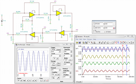
Greetings! My name is Gilberto and i am a graduation studdent of automation engineering from Brazil. I am having trouble with the understanding of the function and sizing of the resistors Rg and Rf for the bubba oscillator circuit described on the application report SLOA060 - march 2011, page 17 figure 18. The oscillator porpuse is to develope a current inverter thru the H-bridge topology, oscillating on a frequency of 60Hz. The RC filter i've calculated from the equation 'f=(1/(2*pi*R*Cs))' in order to oscillate on this particular frequency is built up by either a 26,5kOhm resistor and 100nF capacitor or a 3,9kOhm resistor and 680nF capacitor, for all four RC filters. The op amp i am going to use for this circuit is the same presented by the application note, TLV2474. I'd apreciate very much if you could help me with this and even tell me if this circuit is able to fulfill the task. Thank you very much in advance!!
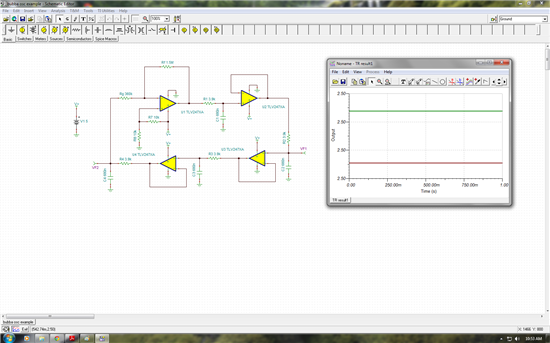
I tried to simulate it on TINA-TI and failed, below is the circuit schematic i designed:
And the transient simulation result:


