This thread has been locked.

If you have a related question, please click the "Ask a related question" button in the top right corner. The newly created question will be automatically linked to this question.

Enquiry about current measurement

Other Parts Discussed in Thread: INA213, INA270

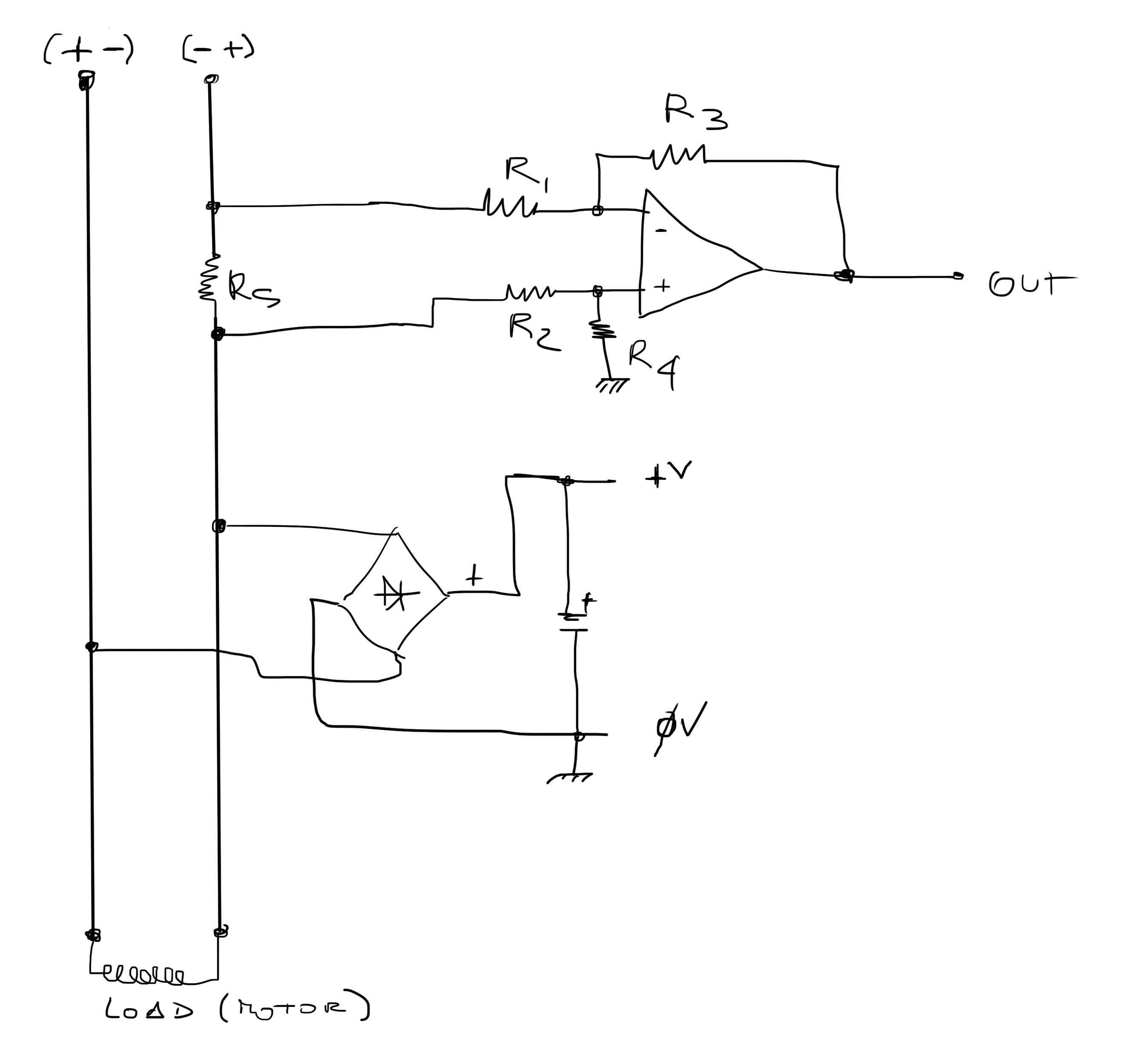
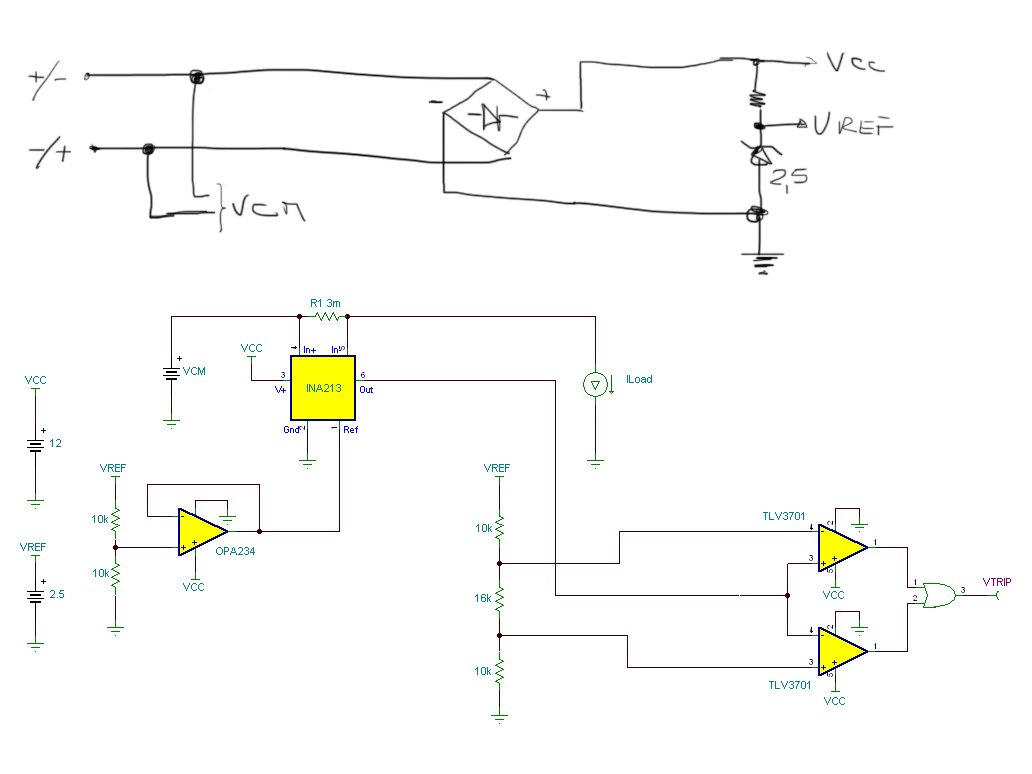
Hi, my problem is this; i need to measure current over DC circuit where the DC power polarity is casual. It is assimilable to the AC circuit and the shunt resistor go one time on the high side and one time in the low side. So, i have one shunt resistor of 0,6ohm value and the maximum power voltage of DC circuit is 12V. Because i need to power my measurement circuit with power over measured circuit, the Common mode voltage go one time to 0V and next time to 8/9V respect to ground. My question is: what is the best way to make the shunt reading floating respect the ground?

I try to explain with a drawing.

Thank's

Neri T.

  • Hi Neri,

    Thank you for your question regarding current sensing...your drawing was helpful, thank you for including it...to best help you I have to ask a few questions:

    Can you plesae confirm the following?

    • Do you have a stable 12V power supply for the amplier?  (I am not sure if you are trying to create the 12V DC supply or if you already have it)
    • My understanding is that your common mode voltage range is from 0V to 8 or 9V is this correct?  (If the common mode range is within the power supply voltage for the IC this gives us many more options to consider...if the common mode voltage range can exceed the power supply voltage we will need to consider a current shunt monitor or a difference amplifer similar to what you have drawn)
    • What is the expected current range through the 0.6 Ohm shunt resistor?
    • Is the current through the shunt resistor uni-directional or bi-directional?
    • What is the bandwidth of the signal to be measured across the shunt resistor?
    • What is the bandwidth (or rise/fall time) of any common mode signals?
    • What is the desired output voltage range you expect from the IC?
    • What resolution and or accuracy are you hoping to achieve at the minimum and maximum current levels?


  • Hi,

    the power supply is generated when the measured circuit is powered and the delay time to power the amplifier is not important. The maximum value of power voltage generated is 12-1,2(rectifier)-1,5(Linear Voltage Regulator)=9,3V 

    The common mode voltage range is 0 to 9V

    The current through the shunt is max 5A

    The current in the shunt is bidirectional (in the real circuit i have inserted another bridge to rectifie the signal)

    The rise time of common mode signal is 5/7milliseconds

    The desired output voltage range from IC is 0 to 5V ( the output is connected to other amplifier with fixed reference wich make triggering when the output of first IC go over 2,4V)

    The resolution is not important because i need only to measure when the current go over 3,5A ( the object of this circuit is to make shutdown of motor when the current go high respect the nominal motor current absorbtion)

    In the circuit, before the shunt, i have on relais wich break the power to the motor. When relais commutation occurs the relais go to self powering until the power is off or is inverted.

    I can't insert in the circuit another powering metod. I have only two wire to make motor powering, current measuring, measure circuit powering and motor break. This is a special method to complicate a simple current measuring circuit but the my final client ask this. It is possible ( i have build a functional circuit prototype but my objective is to simplify the circuit and cut the production costs.

    Thank's

    Neri T.

  • Hi Neri,

    Thanks for the additional information...what I understand is that you will have a 9.3V supply available for the IC's used in this application.  I also understand that you are looking to measure the load current to see when it exceeds 3.75A, then you will trigger a relay to disable the load.  The circuit below uses a current shunt monitor similar to a difference amplifier to monitor the shunt voltage.  Because you have a single power supply the output of this diffamp circuit needs to be biased above ground to allow for the bidirectional load current...this is the reason to add a reference voltage to the REF input of the INA213.  The REF input of the INA213 also requires a very low impedance to maintain accuracy and this is why I have buffered the voltage divider output.  I chose INA213 as it will operate over the supply range and common mode range you indicated.  The INA213 has a gain of 50V/V (this is the lowest gain in this particular family of amplifiers).  I recommend that you reduce the shunt resistor from 0.6 Ohms to 3 mOhms to accomodate the gain of 50.  The output of the diff amp will now be centered around the reference voltage of 1.25V and will swing to 1.8V when the load current is 3.75A and likewise it will swing to ~0.7V when teh load current is -3.75A.  This output can then be fed into a window comparator to determine when to turn on or off the relays.  Here is a schematic of this circuit:


    Here is a simulation result at Vcm = 0V:

    Here is a simulation result wiith Vcm = 9V

    Please let me know if you have additional questions.

  • Hi,

    yes, i have one little question about this solution. I have not understand, in your reply, if you have considered correctly the powering of system. I try to send you the schematics about the connection wich i go to make in the real circuit. (Sorry for handwriting...)

    I dont know if INA213, connected to virtual ground, shift the output when the power VCM change the polarity and, accordingly, the shunt go on the high side or low side of load. In the datasheet i have read about INA213 give measurement independently to the supply but in common mode the reverse voltage is -0,3V respect the ground. It is not more correct INA270 ? 

    Thank's on advance for reply,

    Neri T.

  • Hi Neri,

    The INA213 behaves like a difference amplifier in that it rejects the common mode voltage.  Below I have included a few busier graphics, the first image is a more detailed schematic that shows how I configured the power supply / bridge relative to the INA213.  The areas highlighted in red are shown in the simulation results...Below the schematic is the simulation result that shows the window comparator will trip when the load current exceeds +/-3.75A.  A possible area of concern is the negative common mode voltage being applied to the INA213 (highlighted in red in the simulation results)...to limit the current into the INA213 inputs to 5mA maximum in the highlighted region I added the two resistors in series with the INA213 inputs...50 to 100 ohms would be typical values for these resistors.  The input source I used was a 12V sine wave with 50Hz frequency...if this is not correct you will need to provide me with additional information on the source waveform...to simulate the load I simply used an inductor with a little DCR.  I chose the inductance value such that during the peaks of the VLine input the load current would exceed 3.75A and the comparator would trip...I did this to demonstrate functionality of the overall transfer function...if you are interested in using the same simulator I used you can download a free version here

    http://www.ti.com/tool/tina-ti