This thread has been locked.

If you have a related question, please click the "Ask a related question" button in the top right corner. The newly created question will be automatically linked to this question.

OPA735 Inverting amplifier problem

Other Parts Discussed in Thread: OPA735

Hi All,

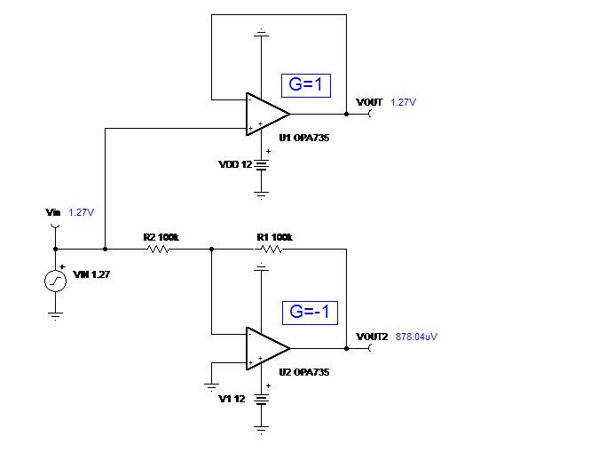
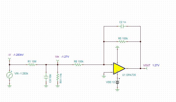
one of my power supply project am using OPA735 as unity gain inverting amplifier configuration with single supply (+12V)

my input to the inverting input is -1.27V max, and non inverting input is grounded, my question is in this case whether this will give inverted output of -1.27V or not?

please check attached schematic,

  • Saravanakumar,

    Unity-gain (G=1) is different than an inverting gain (G=-1) configuration you use in the circuit above.  Thus, if you apply an input of -1.27V, you should expect the output of +1.27V (Vout=Vin*G=(-1.27V)*(-1)=+1.27V and NOT -1.27V;  if you want to get the output to follow the input, you must place the circuit in a follower configuration (G=+1) - see below.

    However, the output in linear amplifiers may never swing beyond supply voltage and it's always defined in terms of swing with respect to its rails.

    If you truly need the output to be at -1.27V, you must use a dual supplies (supplies do NOT need to be symmetrical) with the negative rail at least 50mV higher than your desire output (-1.32V) - see PDS table below.

  • Marek,

    sorry Marek, there is small confusion in the question  i asked in previous post

     in my case am expecting output of +1.27V, just invert the negative input (-1.27V) to positive output(+1.27V) for next stage circuit,

    but for -1.27V input am getting +405mV output in output, this is input may not -1.27V always depends on output of my power supply this may vary but expected output from my power supply is -1.27V, this -1.2V converted into +1.27V and feed to the power supply control circuit.

  • Saravanakumar,

    I believe there are some other issues with your circuit configuration as I am skeptical that you really apply -1283V DC at the input, -Vin, of your 10Mohm to 11k||100k voltage divider; that is what it would take to obtain -1.27V at the input to R8 (see below);  if this is really the case, how do you exactly generate required high voltage (transformer with rectifier)?  If so, please use a scope to confirm that the -1.27V input signal is stable as well as make sure that the output is not oscillating as the large gain setting resistors, 100k, are prone to make circuit unstable.

  • Marek,

    one thing i noticed in my circuit, if i isolate this inverting amplifier section from next stage power supply circuit, and i tested with providing negative supply externally, in this case its working properly, but if its get connected with power supply regulator feed back pin its not working properly,

    please find the complete schematic below