This thread has been locked.

If you have a related question, please click the "Ask a related question" button in the top right corner. The newly created question will be automatically linked to this question.

OPA836 linear output range question

Other Parts Discussed in Thread: OPA836, OPA2684, THS4521, OPA2674

I note two facts about the OPA836:

- The output range is only specified in the datasheet at a gain of +5

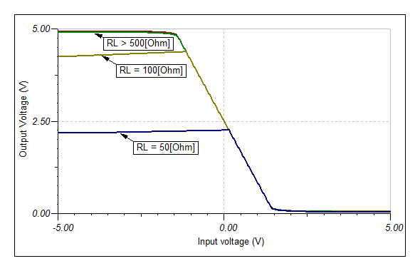
- The PSPICE simulation of an inverting amplifier at low gains seems to show saturation effects well within the datasheet linear range (0.2 to 4.75 at 5V supply). [In particular, I am looking at G = -1.65, VCC = 5V, Vin+ = 2.728V, Rf=1.65k, Rg=1k, Vsource=4.238 V +Vac, then the output AC gain is less than expected 1.65,]

My real question is, is the datasheet guaranteed linear output range spec actually something I can count on at an inverting gain of 1 or a bit more??? Or is there some kind of intermediate-stage signal swing limitation in the OPA836 that I need to worry about.

Of course, I will build a prototype and see. SPICE is just for picking the general form of the circuit and which parts to use. But, I'd like to have some more confidence that I am going in the right direction by picking the OPA836.

If anybody can confirm the 0.2 to 4.75V output range for 5V supply with G=-1 (or a bit more like I need), I would appreciate to hear from you. Thanks!

[p.s. In case you are wondering about the DC bias point mentioned above, this is for a unipolar pulse application.]

  • Hello Gerard,

    Output swing is typically dependent on load, not gain. The reason it was specified in a gain of +5 is so that the input common mode range is not causing any clipping when we are measuring the output.

    That being said the first thing I notice is that your Vsource is 4.238V and Vin+ is 2.728V. Running through the math, the DC operating point at the output will be sitting at 0.2365V. You can quickly see that any AC signal riding on top of this will be bumping against the negative rail and start to saturate.

    If you want the output to be biased to mid-supply for maximum swing, then you should bias the non-inverting input to [2.5V-(4.238V*-1.65)]/2.65 = 3.582V. This sets the output DC operating point to mid-supply and the AC gain to the expected -1.65V/V or 4.35dB.


    However, this will only work for small AC signals because the input DC operating point is now high. The max signal the amp can handle is about 2.7Vpp around a 4.238V DC offset.

    The only way to fix this is to reduce the DC level of the input signal or modify the circuit slightly. Is this fixed at 4.238V? Also what is the peak-to-peak AC signal?

    Regarding the original question, the OPA836 can indeed swing from 0.2V to 4.75V for a load of 1kΩ. However, as you start to decrease the load, the swing capability will also decrease. This is also apparent in the SPICE model, but the actual values may not be modeled correctly.

    I've included the simulation file below to show a sample biasing scheme to get maximum output swing at -1.65V/V gain without violating the input common mode range spec either.

    2821.OPA836 output swing.TSC

    If any of the specs are flexible then you have a lot more options in how you configure the circuit.

    Let me know if this answered the question or if you need further help.

    Regards,
    Luke Lapointe
    High Speed Amplifiers

  • Hello Luke,

    Thanks for your reply. Here's a few comments/questions back. I think I understand better now having read your post, but if you have any additional follow-up it would certainly be welcome to know it. Sincerely,

                                          Gerard

    Hello Gerard,

    Output swing is typically dependent on load, not gain. The reason it was specified in a gain of +5 is so that the input common mode range is not causing any clipping when we are measuring the output.

    So, just to be sure, the output swing can be same as specifications show (for gain of +5) in a gain of -1 application, right? Because there obviously the input common mode range is not an issue (as long as it is in 0 to 3.8V w/ 5V supply I mean).

    That being said the first thing I notice is that your Vsource is 4.238V and Vin+ is 2.728V. Running through the math, the DC operating point at the output will be sitting at 0.2365V. You can quickly see that any AC signal riding on top of this will be bumping against the negative rail and start to saturate.

    That is true, but in this application the signal has only positive excursions at the output (it is a rarely-occurring positive pulse signal (with some 10's of ns risetime and a exponential decay back to the baseline level with ~100 ns time constant, not undershooting at all). I know this is of course not the usual situation and your comment is geared more to that (I think).

    Regarding the original question, the OPA836 can indeed swing from 0.2V to 4.75V for a load of 1kΩ. However, as you start to decrease the load, the swing capability will also decrease. This is also apparent in the SPICE model, but the actual values may not be modeled correctly.

    That is understandable of course. I was just concerned I was misunderstanding something fundamental about the OPA836, but I think from your reply it's not the case.


    By the way, one more follow-up question from me. What is the relation between OPA836/2836 and THS4521? They seem very similar, is the THS4521 essentially incorporating the same amplifiers? I need also in this design a balanced differential output cable driver (for 110 Ohm characteristic impedance) and am looking for the best scheme for this. It should be single-supply (4V ideally, or up to 5V), have lowest possible quiescent power dissipation (on board, that is, power in the load resistor doesn't matter), and have the largest possible signal swing on the cable (for largest possible dynamic range). Ok these are rather vague specs, I apologize, but any general insights from you would be appreciated. Are there other parts I should consider, e.g. an OPA2684 circuit? I am currently thinking to make a circuit such as fig. 13 of the OPA2684 datasheet (synthetic output impedance line driver) but using OPA(2)836. There will be no transformer (it is not allowable in this application) but that shouldn't matter fundamentally.


  • Gerard Visser said:

    So, just to be sure, the output swing can be same as specifications show (for gain of +5) in a gain of -1 application, right? Because there obviously the input common mode range is not an issue (as long as it is in 0 to 3.8V w/ 5V supply I mean).

    Yes. Assuming the output is biased to midsupply (or 2.475 to be exact) and you aren't violating the input common mode range you can get the full swing.

    Gerard Visser said:

    That is true, but in this application the signal has only positive excursions at the output (it is a rarely-occurring positive pulse signal (with some 10's of ns risetime and a exponential decay back to the baseline level with ~100 ns time constant, not undershooting at all). I know this is of course not the usual situation and your comment is geared more to that (I think).

    I was implying that with the current biasing scheme and DC offset your input signal max can be 0.02V above 4.238V and the input signal min can be 2.7V below 4.238V before the output will start exceeding the 0.2V to 4.75V output limitation.

    Gerard Visser said:

    That is understandable of course. I was just concerned I was misunderstanding something fundamental about the OPA836, but I think from your reply it's not the case.

    Yes, the amplifier should provide full swing under both conditions provided the load is not too heavy.

    Gerard Visser said:

    By the way, one more follow-up question from me. What is the relation between OPA836/2836 and THS4521? They seem very similar, is the THS4521 essentially incorporating the same amplifiers? I need also in this design a balanced differential output cable driver (for 110 Ohm characteristic impedance) and am looking for the best scheme for this. It should be single-supply (4V ideally, or up to 5V), have lowest possible quiescent power dissipation (on board, that is, power in the load resistor doesn't matter), and have the largest possible signal swing on the cable (for largest possible dynamic range). Ok these are rather vague specs, I apologize, but any general insights from you would be appreciated. Are there other parts I should consider, e.g. an OPA2684 circuit? I am currently thinking to make a circuit such as fig. 13 of the OPA2684 datasheet (synthetic output impedance line driver) but using OPA(2)836. There will be no transformer (it is not allowable in this application) but that shouldn't matter fundamentally.

    The OPAx836 are single ended output voltage feedback amplifiers, while the THS4521 is a fully differential amplifier. The THS4521 is based on the OPA836 core but it is using a fully differential architecture. You can learn more about fully differential amplifiers by checking out the High Speed Amplifier Application Notes sticky on the front page (http://e2e.ti.com/support/amplifiers/high_speed_amplifiers/f/10/t/68389.aspx), specifically, the section on fully differential amplifiers.

    As far as line drivers go, the THS4521 may be ok, but there is an output current limitation of +/-55mA into a 50Ω load. This would correspond to about +/-37mA into a 110Ω load which may or may not be a limitation. For higher current drive, the scheme you suggested with the OPA2684 would work well (or OPA2674 for higher current capability). Again there are some good app notes included in the sticky on this if you would like more information.

    Regards,
    Luke Lapointe
    High Speed Amplifiers