This thread has been locked.

If you have a related question, please click the "Ask a related question" button in the top right corner. The newly created question will be automatically linked to this question.

XTR 117

Other Parts Discussed in Thread: XTR117

Hi,

I have assembled the circuit of XTR 117  on breadboard as provided on pspice.

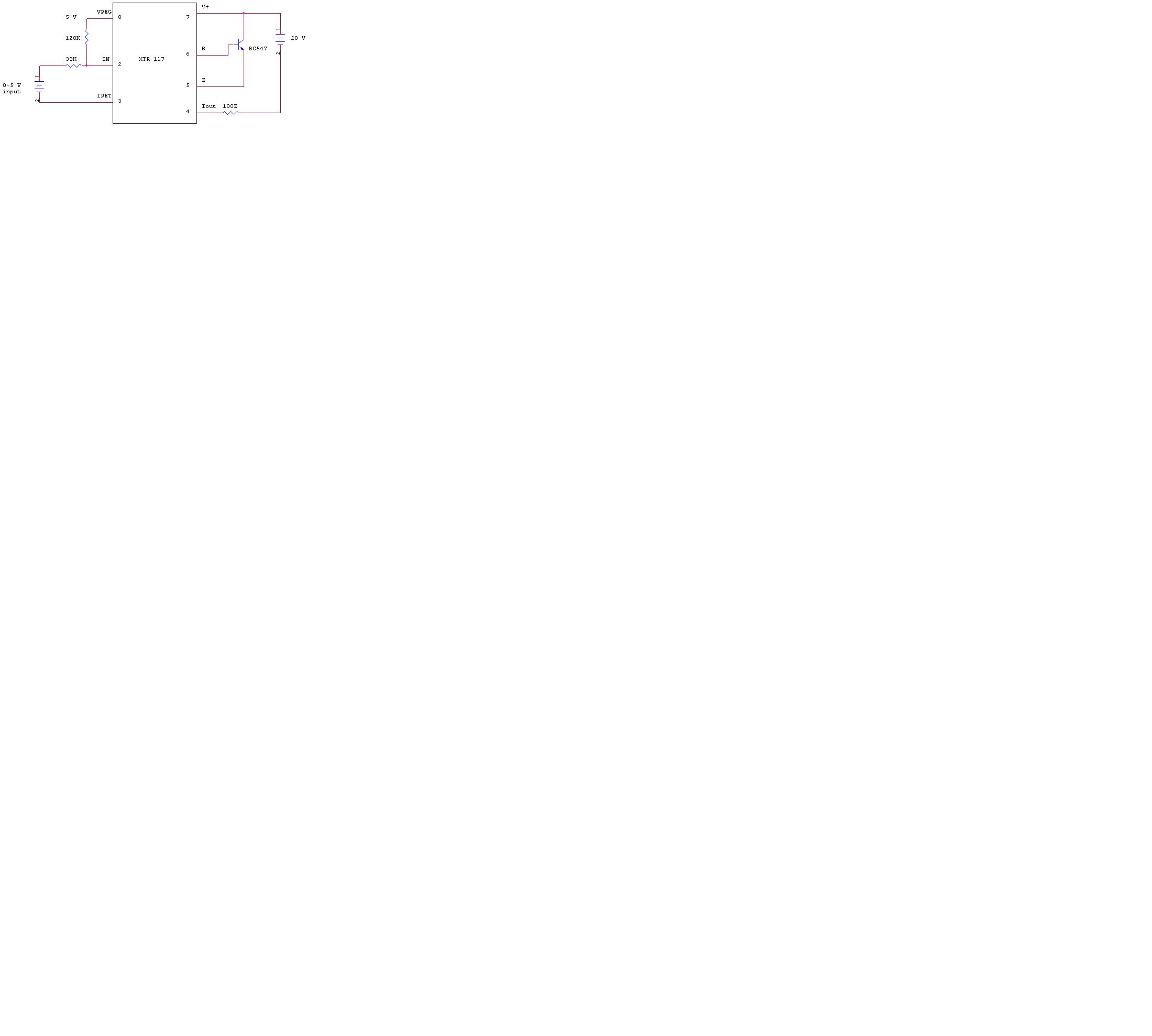
Input voltage of 0-5 V is provided through variable power supply.(Positive terminal of supply connected to IN terminal  via 33K resistor and negative terminal of supply connected to IRET.)

Supply voltage is 20V, load resistor of 100 E and BC 547 transistor is used and results are as mentioned below.

Voltage at pin no. 2- 0.15 V to 0.5 V (for 0 to 5 V input)

Voltage at pin no.3- 0V

Voltage across load resistor(100 E)-0.06 V (constant for entire input range)

 Voltage at base terminal of transistor- 3.8 V (constant for entire input range)

Voltage at VREG terminal- 5.24 V (constant for entire input range)

Kindly check and suggest.

Thanks,

paddy

  • Paddy,

    Can you attach an image of your circuit schematic to help us understand how the XTR117 is configured? Do you have a method to test if you transistor is functional (has not been damaged)? I would also double check the pinout of the transistor to ensure that it is installed properly. The transistor should be completely turned on if the base voltage is 3.8V and there is only 0.06V across the load resistor. 

  • Hi John,

    I am really sorry for the delay in reply.

    Please find attached schematic. I have assembled it as mentioned in datasheet. Can transistor is the  only reason for non functionality of the circuit? Can you please suggest what another things I need to check to get proper results.

    So that I will check it again and update you the results.

    Thanks,

    Paddy

  • Paddy,

    Due to the USA holiday, I will jump in with a response. Your schematic did not seem to come through. Please try again.

    I agree with John that the symptoms seem to indicate a problem with the transistor. Try replacing or removing the transistor from the circuit. Do you have a second XTR117 IC that you can try?

    Be sure that the voltage used at the input of the 33k resistor is floating and not connected to pin 4 in any way, such as on the earth connection of the power supply.

    Regards, Bruce

  • Thanks for the advice Bruce!!!!!

    Please have a look on attached schematic.

    I do have another XTR 117. I will try this with another XTR 117 and your suggestions.

    Thanks again for your kind support!!!

    Regards,

    Paddy 

  • Can anyone tell me what that the Vloop means and do we have to use ıt in our circuit  i mean do i have to supply with 24vdc power supply?(4-20 mA Current loop transmitter page 1 figure 1) http://www.ti.com/lit/ds/symlink/xtr117.pdf

  • Hi Aykut,

    Vloop is the loop supply and is absolutely necessary in a 4-20mA current loop system. Two wire transmitters such as the XTR117 sink current from this voltage source in order to transmit information and also use this to supply their internal circuitry.