This thread has been locked.

If you have a related question, please click the "Ask a related question" button in the top right corner. The newly created question will be automatically linked to this question.

DC Power Line Sinusoidal ripple/noise Injection

Other Parts Discussed in Thread: OPA548, TINA-TI, OPA564

Dear All,

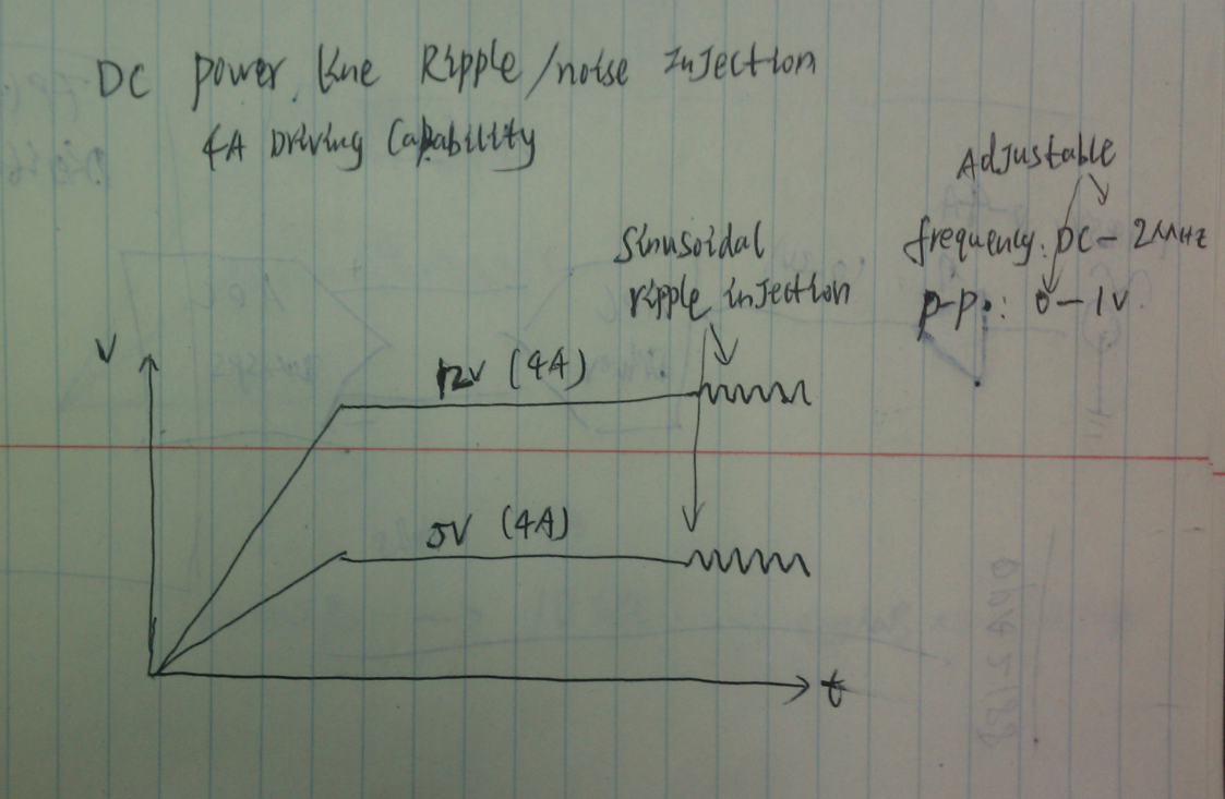
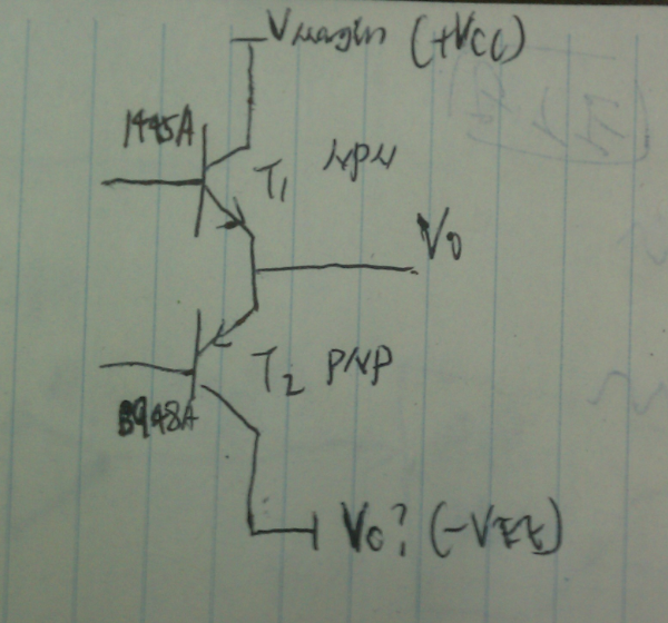
I encounter a technical difficulty on how to inject sinusoidal ripple/noise into DC power line. The design requirement is let's say I have 12V DC or 5V DC power line, each power line has 4A driving capability. I need to inject sinusoidal waveform with adjustable frequency and peak to peak voltage into these 12V and 5V power line to simulation power line ripple/noise situation.  Sinusoidal waveform can be easily derived from DDS (Digital Signal Synthesizer), but signal output from DDS is relative low in power and voltage level. How to inject such Sinusoidal waveform into power line is big challenge to me. Some people says maybe I can use PNP and NPN Power Transistor pair to build a power amplifier but I am not sure how to properly use discrete transistors to build such power amplifier.

Any body has experience or idea on how to do this? Thanks. Please refer to below picture for illustration on what I am trying to do (I hand drawing on a paper).

Ripple/Noise Injection illustration 

PNP NPN pair amplifier

  • Hi Xiao,

    You could use a power operational amplifier as a non-inverting summing amplifier. You would sum the dc level with the ac ripple you wish to impose on the dc line. You can see the general principle illustrated in the attached schematic diagram using the OPA548.

    Finding a power operational amplifier that can provide the 4 Ampere nominal dc level, plus the ac ripple current up to 2 MHz is a challenge. Our OPA548 can be used in this manner, but it doesn't have enough bandwidth to support the 2 MHz ac ripple need. There may be another power operational amplifier by another manufacturer that does meet both the current and bandwidth requirements. You may want to check on line and see if there is amplifier that would meet all your requirements.

    You show a simplified complementary NPN/PNP output stage that at one time was common in operational amplifiers. It is conceivable that you could team a pair of complementary high-speed (RF) power transistors with a high-speed operational amplifier and get the current and bandwidth you need. The transistors would follow the operational amplifier output and the emitters would feed back to the inverting input. Some form of dc bias would be needed to bring the transistors into class AB operation and very likely the entire amplifier would require compensation to keep it stable. This approach would require a lot of design effort.

    Regards, Thomas

    PA - Linear Applications Engineering


  • Hi Thomas, 

    This for the detailed explanation, that's really helpful. BTW, May I know what's the simulation software you using in attached pic? Thanks.

    Regards,

    Wang Xiao

  • Hi Xiao,

    The OPA548 summing circuit was simulated using TI's free, TINA-TI Spice simulation software. It is very easy to learn and will allow you to create and simulate your own circuits. Here is the link where you can download the TINA-TI:


    http://www.ti.com/tool/tina-ti&DCMP=hpa_amp_general&HQS=Other+OT+tina-ti


    I also have attached my original OPA548 simulation circuit so you can evaluate the summing amplifier idea.

    Regards, Thomas

    PA - Linear Applications Engineering

    OPA548_non-inv_sum_01.TSC
  • Hi Xiao,

    I was discussing your application with one of my colleagues who has a good deal of knowledge about power line communications (PLC). He thinks a possible solution to your application would be to couple, via a capacitor, the ac signal to the dc line. The impedance of the dc line may be very low at low ac frequencies but likely increases as the frequency is increased. You would need to amplify the ac signal from your DDS so you would still need a fast, high current operational amplifier - but maybe not as high of current as my summing circuit approach.

    The OPA564 has a rated output current of 1.5 Amps, a supply voltage range of 7 to 26 V and a gain-bandwidth product of 17 MHz. This amplifier may be able to deliver enough current to the dc line well enough to simulate the ac noise condition you are after.

    Regards, Thomas

    PA - Linear Applications Engineering


  • Hi Thomas,

    Do you think OPA564 will deliver enough power for capacitor coupled ripple injection? Why I am asking this is because one of our U.S. design team designed a tester board with such method for ripple/noise injection about 15 years ago. They was exactly using the transformer and capacitor coupling method to inject sinusoidal waveform. This design was using very bulky audio amplifier (4KW) for low frequency injection and RF amplifier (75W) for high frequency injection and the design declare that able to inject sinusoidal waveform up to 100Mhz. However, we have done some calculation and analysis and conclude that even with 75W RF amplifier, the frequency can only inject below 1Mhz. (I have attached our analysis document for you. And this setup is very bulky and old. That's why I was signed up to design a compact Power tester with modern electronics which capable for Voltage margin control, 20MSPS high speed voltage/current sampling and ripple/noise injection. The ripple/noise is the most challenge part for me.

    One more concern on capacitor coupled method is at low frequency For example DC - 1khz, However if OPA564 method can prove works for frequency higher than 1Khz, that's will be great already. Because I have fully control on power margining (1V - 14.5V with 10mV step), I am thinking modulate DC/DC converter pwm output up and down to simulate low frequency ripple condition (less than 1khz). But higher frequency especially higher than PWM frequency. This method is no achievable. 

    I am still in research on suitable method. You have helped a lot already. Appreciated.

    Regards,

    Wang Xiao

  • Hi Xiao,

    Your feedback is helpful in understanding the challenges of your application. The impedance looking into the dc line is what will dictate how much current the ac amplifier would have to provide. It does sound like that impedance can be very low based on the description of the AF/RF power amplifier solution and the high amounts of power it had to deliver when driving the line. I question if the OPA564 rated current (1.5 Amps) would provide deliver enough current for your application.

    There is another company that TI has no association with that specializes in high-power operational amplifier products, Apex Microtechnology. Take a look at what they have to offer; some of their amplifiers provide both high current and have wide bandwidth. They may have a suitable power operational amplifier that could be applied in the non-inverting summing amplifier circuit I provided, or be used to inject the ac current directly into the dc line via a coupling capacitor

    Regards, Thomas

    PA - Linear Applications Engineering

  • Hi Thomas,

    Thanks for the help. I am contacting Apex look for suitable power amplifier

    Regards,

    Wang Xiao

  • Hi Thomas.

    May I know how did you observer AM1 and Vout together, I can only observer voltage by oscilloscope.

    By the way, I used Tina-TI.


    Thank you.

  • Hi Hamilton,

    I understand your question to mean AM1 and Vout in the TINA simulation results I had posted. AM1 is one of TINA's types of ammeters. It appears as a horizontal line with an arrowhead pointing to the right. TINA refers to it as the "current arrow" and it is listed within TINA's "Meters" pull-down. I use the "open circuit" symbol in the "Meters" pull-down for the voltage measurement.

    When both of these meters are used in the circuit TINA will show their measurement results whenever you perform an dc, ac, or transient analysis.

    Regards, Thomas

    PA - Linear Applications Engineering


  • Hi Thomas.

    That's very kind of you, after your explanation, I used transient analysis to get the AM1 value I want.

    Thanks.