This thread has been locked.

If you have a related question, please click the "Ask a related question" button in the top right corner. The newly created question will be automatically linked to this question.

help , log114 make me crazy.

Other Parts Discussed in Thread: LOG114

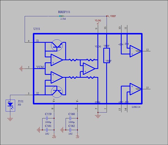
+-5v power .  a INGaAs PD.  connect with log114.   

first. I use adjust the current I1 with 1ua. by adjust the rref to 2.5M.  test the current with keithley 486.

then I connect the PD to I2.    

pd power                            Vlogout     [note1]                       vlogout           I2[note2]     the correct result must be.

 (test by power meter)    (PD directly connet with I2)        ( PD-keithley 486-I2) 

-10.147dBm                          -3.1v                                            -2.99v        100.38ua                       -0.75V

-19dBm                                 -2.9v                                             -2.14 v          10.01ua                      -0.375V

-30.18dBm                            -2.6 v                                            20mv          1ua                               0v  ( maybe 20mv is correct)

-39.833dBm                        -1.5 v                                              0.9v             101na                          0.375V           

use the simplest circurt:

[note1]  means.  I connect the PD directly with the Pin I2

[note2]  means  I connect the PD one pin to GND, the other to keithley 486 , and connect keithley 486 with log114 Pin I2 to measure current.

I test many times.  change the PD, change the PCB.   and the result is the same. I am going to crazy. pls help me.

  • hello everybody.  I change the PD connect to I1, and change Iref to I2. then I get the below list.

    pd power                            Vlogout     [note1]                       vlogout           I2[note2]     the correct result must be.

     (test by power meter)    (PD directly connet with I2)        ( PD-keithley 486-I2) 

    -10.147dBm                          0.75                                             0.75v            100.38ua                       0.75V   right

    -19dBm                                  0.375                                           0.375            10.01ua                      0.375V  right

    -30.18dBm                            0 v                                           0mv                  1ua                               0v                  right

    -39.833dBm                        -2v                                             -2v                      101na                         - 0.375V          

    when the I1 < 1ua, the voltage out is incorrect.   what's the problem?? 

  • Hello Wei,

    Your LOG114 circuit implementation is simple enough and VLOGOUT should follow the core LOG function, VO = 0.375 LOG (I1/I2). Any gross deviation from the function indicates a bigger problem in the circuit. That is the case for your circuit.

    A common problem that I find is the user hasn't properly connected the backside thermal pad in the circuit. It must be connected (soldered) to V-. In your circuit that would be the -5 V supply. Another common issue is board cleanliness, or lack of, but that is most often associated with errors at low current levels. We find hand cleaning the board with solvents can produce marginal LOG performance and ultrasonic cleaning is most often required. Then there is always the possibility of ESD damage to the integrated circuit, if proper ESD precautions weren't observed during handling.

    Be sure you obtained your device from a qualified TI distributor. There have been problems with gray market semiconductor products ending up in customer circuits and not performing to expected levels.

    Regards, Thomas

    PA - Linear Applications Engineering

  • Wei,

    It should not matter which input I1, or I2, you decide to use as the reference input and current input with the understanding the LOG114 VLOGOUT output voltage depends on which current is in the numerator and denominator of the equation. Connected either way VLOGOUT should produce the correct voltage from a properly operating LOG114. The behavior at 100 nA is completely incorrect indicating a major problem with the circuit. See my comments in the previous post.

    You may want to obtain a LOG114 evaluation module (EVM), or at least review the information in its document. Although it is set up for single,+5 V operation, having one would allow you to evaluate the LOG114 on a proven PC board with your photodiode. You can find the LOG114 EVM information here:

    http://www.ti.com/tool/log114evm

    Regards, Thomas

    PA - Linear Applications Engineering