This thread has been locked.

If you have a related question, please click the "Ask a related question" button in the top right corner. The newly created question will be automatically linked to this question.

How to read the output of an Optical Encoder (Motor control)


Hi Guys!

I need some technical help in answering the below:

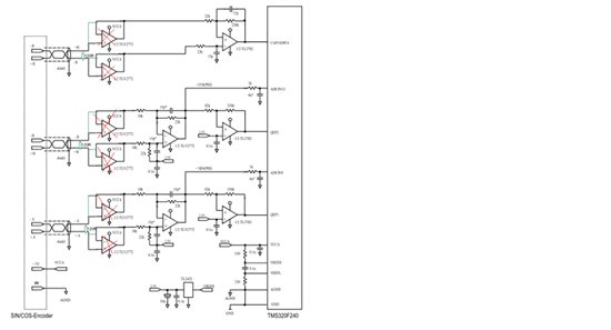
The application has an encoder which has a differential output and it is buffered then amplified (put in mid rail and filtered), see channels A,B,R in the below schematics. The question is, can the buffer stage be removed? (see app.note SPRA496).

Instead of the buffers we want to use a 120ohm termination resistor and remove the buffers. Do you think it can be done? Or there may be impedance mismatching?

For differential analog line interfacing (HEIDENHAIN for example, used for sin-cos encoder, up 10meter cable lenght): would you consider using this high impedance buffered interface for analog signal, or a 120Ohm termination resistor and more simple low cost interface as depicted below?

Please advise,

Thanks,

Gianni


  • Hi Gianni,

    Replacing high impedance buffers  by 120 ohm termination resistor will attenuate the differential signal by a factor of [120/(120+2*Rs)], where Rs is the sensor output impedance.

    I have another concern about this circuit. What happens if common mode output of the sensor is deviated from mid supply? You may consider using a differential amplifier with independent output common mode. Please see the circuit below. Rf and Rg may be adjusted to get the desired signal swing. For single ended ADC, complementary signal output may be neglected after the filter.


    Regards,

    Amal

  • Hi Gianni,

    Replacing high impedance buffers  by 120 ohm termination resistor will attenuate the differential signal by a factor of [120/(120+2*Rs)], where Rs is the sensor output impedance.

    I have another concern about this circuit. What happens if common mode output of the sensor is deviated from mid supply? You may consider using a differential amplifier with independent output common mode. Please see the attached circuit below. Rf and Rg may be adjusted to get the desired signal swing. For single ended ADC, complementary signal output may be neglected after the filter.


    Regards,
    Amal.

    Diff amp.vsd
  •  I agree with your concerns. Thanks a lot. for your suggestion