This thread has been locked.

If you have a related question, please click the "Ask a related question" button in the top right corner. The newly created question will be automatically linked to this question.

LM675 automatic gain control

Other Parts Discussed in Thread: LM675, OPA454, OPA548, TINA-TI

I am looking for a way to adjust the gain into an LM675 so that the output is exactly proportionate to the input, but with more power and higher voltage.

I have a weak signal input that is 5 VAC and 30-70Hz from a voltage divider. It cannot carry any burden.  

I would like to drive some meters that like to see 120V and they have a bout 2-4 watts of burden on the circuit.

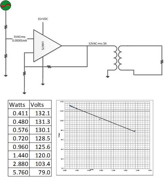
I have assembled a circuit board with an LM675 feeding a 1:10 step up transformer. The 12VAC output will be 120VAC with a direct replication of the input waveform.

The problem is that when the burden changes, the output voltage changes.

Is the solution some sort of circuit that will feed back the difference between the input to board and the output after the transformer and adjust the gain?  

Or is the solution a more digital approach using two ADC's, an MCU and a DAC?

Any hint would be appreciated.

I have fabricated and tested this circuit with the results listed below.

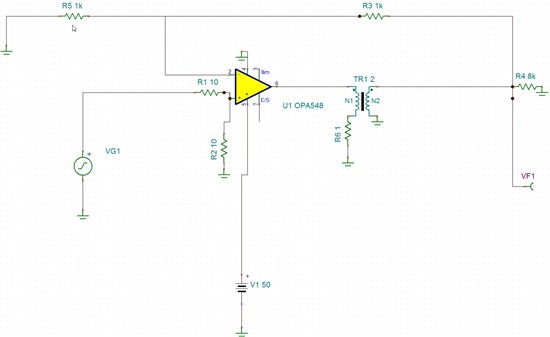
My thought on this is that maybe I could sense the output of the transformer, and use a voltage divider to feed it back to the negative input on the LM675?

Another thought on this is that maybe I do not need the transformers, which I think are contributing to the voltage drop. Maybe I use a high voltage OPA454 which is a 100V amp. Then I just have the output already producing the 69VAC. But even with that, I am not sure the system will not still drop voltage under load.


  • Could someone at least tell me I am crazy, or something?

  • Hello Curt,

    The drop in the transformer secondary with load seems excessive. Are you sure the transformer is rated for the frequency / load that you're using. It seems a bigger transformer would have a lower drop with load.

    Tapping the transformer secondary as the feedback point seems worth a try (to compensate for the loss with loading). However, you may have to do be careful with any phase shift that the transformer may introduce in the loop that could cause instability (I've not personally done anything like that, but you would think that's exactly what is done in switching power supplies where the output of the transformer is sensed and fed back to adjust the PWM switching controller). To get isolation from the secondary you could also use an opto coupler.

    Regards,

    Hooman

  • Hooman,


    Thank you for the reply. You are probably right that the transformer is the problem and not the amp. I am going to try two things:

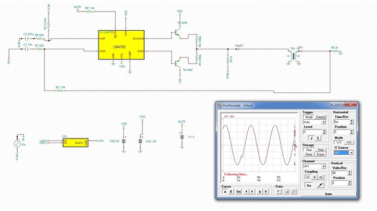
    1) use a high voltage amp (LM4702) to provide an output that is at the 100Vpp that I need so that I do not need a transformer.

    2) Tap the feedback from the output of the transformer and see if I can find a stable feedback resistor and maybe even a voltage divider to bring it down to the level I need. I am encouraged by this solution since it sounds like the simplest.

    Can you look at the LM4702 and let me know if you think that would accomplish a 100Vpp output (69Vrms) at 200mA? I plan to have a source voltage of 125VDC.

    Thanks again,


    Curt Gibson, PE


  • Hi Curt,

    With regard to the LM4702's voltage swing capability:

    LM4702C is rated for 51VRMS (0.05% THD) with +/-75V supplies. That represents 144Vpp which should be plenty for your needs (100Vpp) even with your lower 125V DC power supply. However, keep in mind that the output current is only 5.5mA typically. So, you'd need current boost MOSFET or BJT's on the output if you need more current.

    These application notes may be useful:

    http://www.ti.com/litv/pdf/snaa045a

    http://www.ti.com/litv/pdf/snaa031a

    http://www.ti.com/litv/pdf/snaa058b

    Regards,

    Hooman

  • After looking further, I have decided to use the OPA548 because it has a Tina-TI model that I can work with. The LM675 does not (or I cannot find).


    Even with the model, I cannot seem to find the right combination of resistors to provide a sinusoidal output waveform. Without that, it is difficult to verify that the feedback loop will work being on the far side of the transformer.


    Is there a company that I can hire to do amplifier design like this?  


  • Hi Curt,

    You are correct in that the LM675 does not have a TINA-TI model.

    If you are not getting a sinusoidal waveform (with VG1 being a sine input), what type of waveform are you measuring / simulating? Can you attach a photo / details? If you are talking about simulation only, are you modeling the transformer? You may just attach the TINA-TI (*.tsc) file so that we can take a look.

    I'm sure there are many contractors that do these types of designs if you search for them.

    Regards,

    Hooman

  • Hooman,,,, Thank you.


    I am finally finding that the LM4702 can do what I am asking. I have ordered and received two of these amps from digikey and will build a prototype board based on this. The 4702 application is based on what you told me regarding the mosfet drivers. This is the TI reference design, but feeding a transformer and sensing the feedback from outboard of the transformer. The output is rigid in Tina, so variations in the load do not change the voltage. That may be that the only transformer is an ideal transformer. We shall see on the prototype.


  • Hi Curt, any updates about your project? Thanks.