This thread has been locked.

If you have a related question, please click the "Ask a related question" button in the top right corner. The newly created question will be automatically linked to this question.

LMH6629 Trans impedance amplifier oscillating around 1 GHz

Other Parts Discussed in Thread: LMH6629, TINA-TI, LMH730316

Dear colleagues,


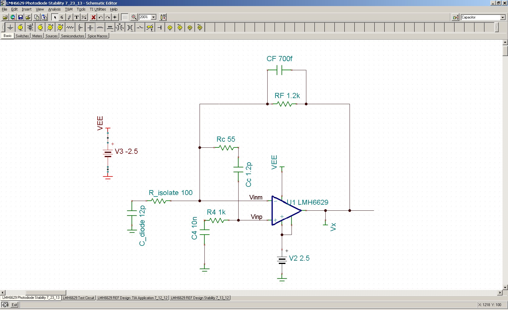
The LMH6629 has been configured as Trans impedance amplifier with the following conditions:

  1. photodiode capacitance 12pF
  2. Feedback resistor 1.36K ohm
  3. Non-inverting input grounded!
  4. ±2.5V power supplies
  5. COMP pin connected to V+ (high frequency mode)
  6. Power down pin floating (disconnected)

I already developed the board.

when I connect feedback capacitor Cf, the output is oscillating around 1 GHz.

I tried several values between 0.1pF to 1pF

Only when Cf cap is totally removed, the high frequency oscillation disappear and the stabilization of the loop achieved by means of a series resistor between the photodiode and inverting input.

I can’t understand this oscillation

Please advise!

  • Hello Natan,

    The speed of the LMH6629 certainly makes it a challenge (especially if your photodiode is some distance away from the LMH6629 inverting input).

    Here are some recommendations:

    1. Please follow these recommendations: http://e2e.ti.com/support/amplifiers/high_speed_amplifiers/f/10/p/183718/669118.aspx#669118

    2. Here are the modifications (R_isolate, R4C4 combo, RcCc combo) which have helped me in the past with this type of circuit when the photodiode is sitting about 1.5" away from the LMH6629:

    1754.LMH6629 Photodiode Stability 7_23_13.TSC

    The most important of these modifications for stability, when the photodiode is placed away from the inverting input, is the R4C4 combo with R4 >=1kohm, as shown. Even if your photodiode is right on the inverting pin, it may be worthwhile to try these modifications. I have also seen the layout being a big factor (my results were with the LMH6629 EVAL baord noted in #1 above).

    Please give it a try and let me know.

    Regards,

    Hooman

  • Hello again Natan,

    Sorry, the modifications I previsouly posted is missing an important element (R_bias for DC biasing) which I had forgotten to include and I've corrected below. My testing was with single 5V supply and I had used two 25k resistor to divide the supply to Vcc/2, on the non-inverting input, which I have shown as 12.5k in your setup with dual +/-2.5V supplies:

    1212.LMH6629 Photodiode Stability 7_23_13 modified 7_23_13.TSC

    Please let me know if you are able to get a stable circuit.

    Regards,

    Hooman

  • Hello Hooman,

    I didn't try yet your suggestion, but I have few comments:

    1)  adding 1Kohm (R4) at the non-inverting input will introduce large noise (further amplified by the noise gain) 

    2) do you think that somehow at high frequency the output node coupled to the non-inverting input, thereby, a positive feedback takes over the loop

    3) the target BW of my system is about 160MHz. from you experience is it achievable?

    4) currently, I am using 8-pin WSON package. may the alternative SOT-23-5 package exhibits more stable performance?

    I appreciate your help


  • Hi Natan,

    I will try and respond to the questions you had raised:

    1) Noise: You are correct about the noise increase. But, I think there are workarounds for that. I wanted to see if limiting the AC impedance of the non-inverting input will quell your instability. If so, one possibility would be to use an appropriate Ferrite Bead (NL1) in place of Rbias, as shown. This way, the DC biasing is satisfied but at high frequency, where instability is a concern, the R4C4 path to ground dominates because of the impedance of the ferrite bead.

    If I compare the simulated 200MHz (bandwidth) noise of the circuit with the non-inverting input grounded vs. the ferrite bead I've used here as shown, the RMS noise increases from ~160uV to ~200uV. So, there is some noise impact but it may not be big enough to concern you:

    Here is the TINA-TI simulation file with the ferrite bead above if you like to investigate the noise performance. You may have to experiment with the ferrite bead you choose (I just used what I had availble):

    2148.LMH6629 Photodiode Stability 7_23_13 modified 7_24_13.TSC

    Some Ferrite information (Murata):

    2) Root Cause: My suspicion is that we are dealing with the reactive output impedance of the emitter node of the internals of the LMH6629 BJT. This is somewhat discussed in this Application Bulletin and in the link below, but this is only a hunch:

    http://www.ti.com/general/docs/litabsmultiplefilelist.tsp?literatureNumber=sbaa045

    "Figure 4 shows how the emitter follower can oscillate due to reactive output impedance. Figures 5 through 7 show calculated results for different conditions when a simple emitter follower is driving a capacitive load which illustrates this oscillatory tendency".

    http://www.linkedin.com/groups/Emitter-Followers-As-Colpitts-Oscillators-2091456.S.139421890

    3) Bandwidth: Yes, with the 12pF photodiode capacitance, that is certainly achievable. LMH6629 Equation 9 predicts close to 200MHz.

    4) Package Difference: I have not compared the two packages. The SOT23 version has an unassembled EVAL board that you could obtain and do experiments with:

    http://www.ti.com/tool/lmh730316

    Regards,

    Hooman

  • Hi Hooman

    sorry for the late response.

    1) I have succeeded to de-Q the oscillation by a bead like you suggested above. regarding the noise, the penalty is indeed negligible.

    2) only with the presence of the bead I was able to change the capacitance Cf and to see the intrinsic dynamic features of the amplifier versus feedback.

    3) however, it is interesting to know whether the LMH6629 amplifier can be used like a pure classic TIA without any bead in order to "kill" local oscillations

    • If yes, I really will appreciate your help to make such design (schema+Layout) 
    • If no, I hesitate to consider the bead as a reliable solution because what guarantee that this oscillation or a new one will not suddenly appear during a sensitive operational work

    Best regards,

    Natan