This thread has been locked.

If you have a related question, please click the "Ask a related question" button in the top right corner. The newly created question will be automatically linked to this question.

LMV7272 input bias

Other Parts Discussed in Thread: LMV7272

Hello,

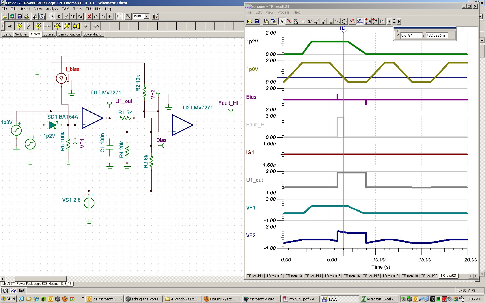
I've just got boards fresh from factory using LMV7272 comparators. Two of them behave strangely. More accurately, I've something I don't understand at the positive input:

I'm using them to check that a 1.2V supply minus 0.2V is always lesser than a 1.8V supply. To get the 0.2V offset I'm using a schottky diode in series with the 1.2V supply, with a 100k pull down to minimize current losses.

At startup, when the two supplies are shutdown I'm measuring at the anode a greater voltage than on the cathode:

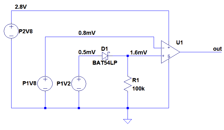
Does someone has any clue? Thanks.

  • Hello,

    May be you can describe what the result of what you are observing / pondering to make it easier to give assistance.

    What is the effect of the voltage measurements you have made when the power supplies are turned off? Does something misbehave or get damaged?

    Regards,

    Hooman

  • Hello Hooman,

    Thanks getting back on my question. To clarify my drawing:

    - P2V8 is a "always on" supply (typ. value of 2.8V) whereas P1V8 and P1V2 are two bucks supplies (1.8V and 1.2V nominal when activated). I'm using the 'out' to:

     1) quickly discharge the P1V2 supply

      2) stop the P1V8 buck

     It's in order to respect an LPDDR2 requirement at shutdown (P1V2 must alway be less than P1V8 minus 200mV) 

    - On some boards (2 from 14 prototypes) the startup sequence doesn't work very well: The LMV7272 'out' is at 2.8V, hence P1V8 can't start...

    If I force the P1V8 with an external 1.8V supply, device ends it power up sequence and works flawlessly until the shutdown order.

    My measurement is on one of those two. Before trying to activate the DC/DC step down, the P1V8 present a 0.8mV voltage, the P1V2 a 0.5mV voltage. After the Schottky I've put to get the -200mV from P1V2, I'm seeing a 1.6mV voltage, which I don't understand. Hence my question about the LMV7272 input bias (10nA in the datasheet), which was the only logical explanation I've got so far.

    Regards,

    Thibault

  • Hi Thibault,

    I agree with your assessment that the 1.6mV measured on the + input is most likely due to bias current flow out of that pin (1nA x 100k = 1mV typically) and in your case you have 1.6nA current. It appears that reducing the 100k resistor should help you. However, you may still have the uncertainty of making sure the 1.8V off-state voltage is lower than 1.6nA * R1!

    Here is what you wrote:

    It's in order to respect an LPDDR2 requirement at shutdown (P1V2 must alway be less than P1V8 minus 200mV)

    Here is what I think you meant based on your schematic:

    It's in order to respect an LPDDR2 requirement at shutdown (P1V2 minus 200mV must alway be less than P1V8)

    Here is one scheme where if you have a spare comparator (U2), you could add a voltage divider path (through R2) to the 1.8V supply so the "fault" (U2 output) could only occur if the 1.8V supply is higher than 0.5V so that the circuit does not prevent the normal power-up. This should also alleviate the concern with the 1.8V off-state voltage competing against the + input:

    Here is the TINA simulation file if you like to experiment with it:

    5516.lmv7271 Power Fault Logic E2E Hooman 8_9_13.TSC

    Regards,

    Hooman